My Account     Contact Us     Cart

Getting the Best Resolution when Importing an Image from a WMS

Using a Web Map Service (WMS) is a great way to easily get up-to-date imagery for your project. An issue you may run into, however, is that a server may not allow you to download images over a certain size (in pixels). The image resolution provided on most servers is usually high enough for most projects but there may be some instances where a higher resolution is needed (e.g. a poster-sized map or a web map that covers a large area).

One possible workaround for this issue is to get several small-area, high-resolution images from a WMS and then mosaic them together to make one large-area, high-resolution image. Here, we will use the City of Toronto Web Map Service to:

  1. Get an image of downtown Toronto
  2. Tile the image to split it into four smaller images
  3. Use the extents of the four tiled images to get four high-resolution images
  4. Mosaic the images to one large high-resolution image


Download an Image from the Web Map Service

First we will get an image of downtown Toronto from the City of Toronto WMS. Click the Advanced Import button on the Geographic Imager panel. Select Web Map Service from the Format drop-down and click Browse. Click Load services from Avenza and select City of Toronto WMS from the list.


Download an Image from the Web Map Service
(Click for larger version)


Select City of Toronto Imagery from the list of layers. Click Select Area then drag a box to zoom in on an area of downtown. Click OK to return to the previous window. There is no need to change the image size because we will use this image to get the extents of a higher resolution image. Leave the other options as default and click OK to load the image, and click OK again on the Advanced Import dialog box. The selected image will now open in Adobe Photoshop.


Tile the Image

Next, let’s tile the image to split it into four separate images. Open the Tile dialog box from the Geographic Imager panel. Choose By Number of Tiles as the Tiling Schema and change Horizontal and Vertical to 2. Change the Horizontal and Vertical Overlap to 3 percent. It’s important to have overlap between the images so they will mosaic properly when the data is transformed.


Tile the Image
(Click for larger version)


Click the Keep Images Open check box to enable it. Choose a name and location to save the tiles. You can save them to a temporary location because they will not be part of the final product. The four image tiles will open in separate tabs.


Estimate a Web Map Service’s Maximum Image Size

Open the City of Toronto Imagery WMS again and select an area. In this service, as with many other services, the maximum resolution is not provided. We can, however, use trial and error to find the largest image that the service will allow us to download. A WMS has a maximum allowed width and height set for an image request. The maximum width is usually the same as the maximum height.

Set the resolution of the image by adjusting the width of the image in pixels under Output Options. First, try setting Image Size to a pixel width of 5000. Height will update automatically based on the image’s dimensions. Click OK and you will see an error that says “Parameter ‘width’ contains unacceptable value” (or height if the images higher than it is wide). OK the error to close it.


Estimate a Web Map Service’s Maximum Image Size
(Click for larger version)


To estimate the maximum width and height allowed by a web service, you can adjust the image size to see when the server returns an error. The maximum width and height for the City of Toronto WMS is about 4000 pixels.


Downloading and Mosaicking Large Images

Next we will use the geographic extents of the four tiled images to download four higher resolution images with matching extents then mosaic the images together. Import an image again from the City of Toronto WMS using Advanced Import. Select an area, click Select Area by Another Document’s Extents and choose the first tiled image from the dropdown menu. The Select Area dialog will display an area matching that image’s area. Click OK to return to the previous screen.


Downloading large images
(Click for larger version)


Enter 3000 as the Image Size. Click OK to add the image to the Advanced Import dialog box. Repeat the above steps for each of the remaining three tiled images.

Creating a mosaic of four images (two by two) makes a single image just under 6000 pixels wide because of the overlap between the tiles (the height will vary depending on the area you selected). This is larger than the maximum size allowed by the WMS. Check the box Mosaic All Files to the Destination Document and select one of the images currently loaded in the dialog window from the drop-down menu. Leave the other options unchecked and select Normal as the Layer Blending Mode. This will merge the four images into a single document.


Mosaicking large images
(Click for larger version)


Avoid Downloading Images Greater than the Maximum Image Resolution

One further consideration when getting imagery from a service is to avoid requesting an image that is higher resolution than the full resolution of the image on the service. In this case, the number of pixels in the image and, therefore, the image size will increase without any increase in the actual resolution of the image.

To see an example of this, get an image from a WMS by zooming in on a small area and downloading images of varying resolution. The pictures below show two images of the same area side by side at different resolutions. The image on the left is 1024 by 870 pixels and the one on the right is 2500 by 2124 pixels but there is no noticeable difference between them. This is because the image exceeds the resolution of the image on the server so the WMS resamples the image to a higher resolution, creating duplicate pixels.


Avoid Downloading Images Greater than the Maximum Image Resolution
(Click for larger version)
 

Styling Your Map in Adobe Illustrator: Objects vs Layers

One of Adobe Illustrator’s powerful yet occasionally confusing features is the ability to apply fills, strokes and Graphic Styles to art at either the Object level or the Layer level. This is extremely useful because you can effectively use Layers to set up symbology templates so that any art that is drawn on a Layer inherits its appearance from that Layer. Confusion often arises when users combine art styles at both the Layer and Object levels, and cannot figure out why their map does not look how they expect it to look. Most of the examples here are going to be based around using the Appearance panel to apply strokes and fills.


Selecting Objects or Selecting Layers

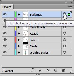
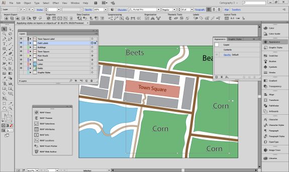
The first decision you have to make is how you select your art. You can either select the layer that the art is on or directly select the art itself. This determines where the changes you make get applied. In order to select the layer, click the circle to the right of a layer name in the Layers panel. You will see that the layer is selected (also known as targeted) by the addition of another circle around the first circle.

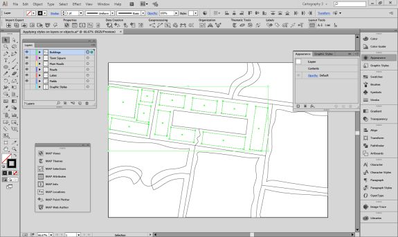
Selected Layer.

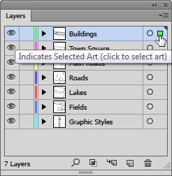
To select all the art on a layer you can either click in the space to the right of the circle, or Alt-click the layer name.

Selected Art.

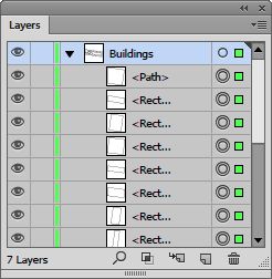
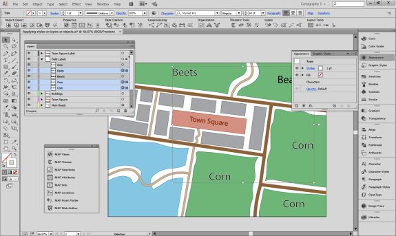
If you expand the layer you can see that the art is targeted rather than the layer.

Targeted Art.

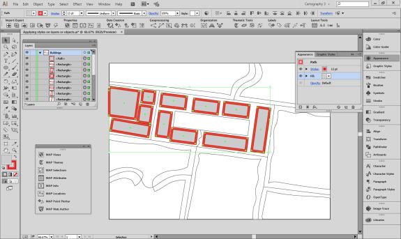
Whichever method you use, you will see the art on the canvas appear as selected.

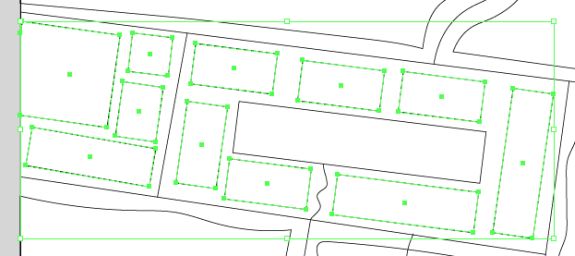
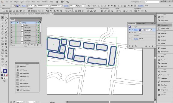
Selected Buildings.

Of course you can select individual art using the Selection tool or clicking to the right of the circle next to the object name in the Layer panel.


Changing Strokes and Fills

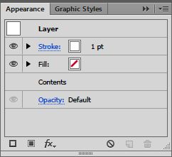
One advantage of selecting art at the layer level over selecting art directly is the access to the strokes and fills in the Appearance panel.

Selected Layer’s Stroke and Fill are unavailable.

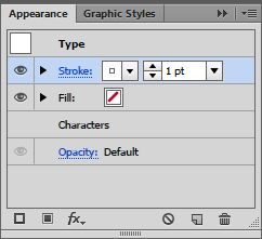
If you select the layer, you do not get direct access to the art’s strokes or fills, however if you select the art you do.

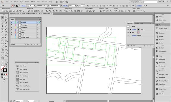
Selected Art’s Stroke and Fill are available.

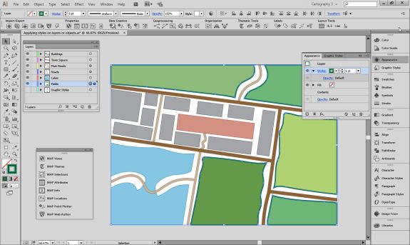
You can add more strokes or fills in the Appearance panel, but if you want to add strokes or fills at the layer level, they are additional to the strokes or fills that are defined at the object level. We can see this if we style the fields individually with different fills, perhaps representing different crop types. We could also add a stroke to each object, or we can add the stroke to the layer. Adding strokes or fills like this is useful when you want to ensure that all art on that layer shares the same symbology.

Object level Fill and Layer level Stroke.

Directly changing the appearance of objects is reflected both in the Appearance panel and the object thumbnails in the Layers panel.

Object appearance is shown in thumbnails.

However, if you add extra strokes or fills at the layer level, these are not shown in the objects thumbnails.

Layer appearance is not shown in thumbnails.

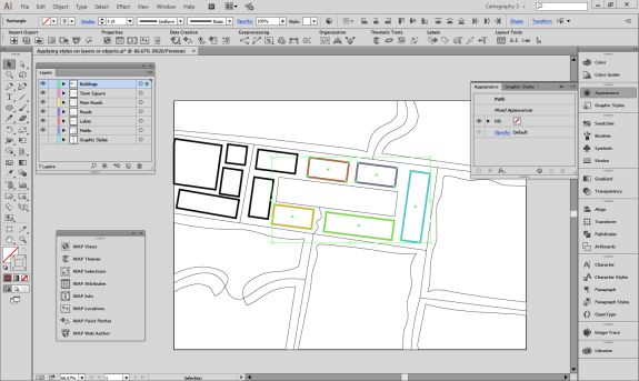
One important consideration is that it is not possible to use the Appearance panel to adjust several pieces of art with different fills or strokes that are applied at the object level. For example, suppose we have changed the colours of several building outlines, and now want to change them back to black. If we select them all, we will see that the stroke option is not available in the Appearance panel, rather it says Mixed Appearances. The fill is still available to be changed as it is the same for all objects.

Objects with mixed appearances.

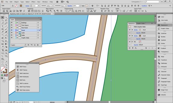
Altering appearances can have different results if applied to objects or layers. A good example is a street style that is created with two strokes. If this is applied at the object level, each object is considered separate and you end up with overlapping paths.

Overlapping stroke styles.

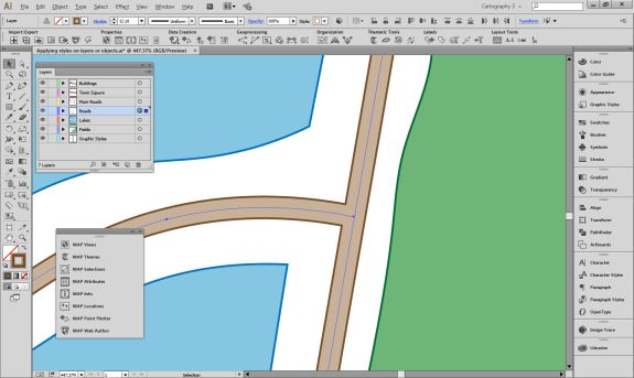
However, if this style is applied at the layer level, the paths are styled at the same time and appear to be merged.

Merged stroke styles.


Applying Graphic Styles

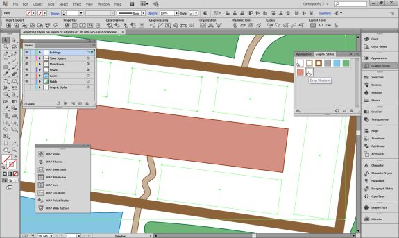
Graphic Styles are great to easily add combinations of strokes, fills and effects to art, and these can also act differently when applied to objects or layers. In the Graphic Styles panel we have a Graphic Style with null fill and stroke, but a drop shadow added. If we try to add this directly to the building art, the null fill and stroke will cause the buildings to disappear.

Object disappears when this style is applied.

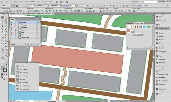
However we can add it to the Buildings layer and the effect is successfully combined with the object level appearance.

Graphic style applied to the layer.


Resolving Appearance Confusion

As mentioned earlier, it is possible to combine object level and layer level appearances. This can get complicated if you have different objects on the same layer with different appearances as well as appearance modifications at the layer level. Trying to work out why you cannot adjust the style of your paths because you are getting Mixed Appearance in the Appearance panel can be frustrating.

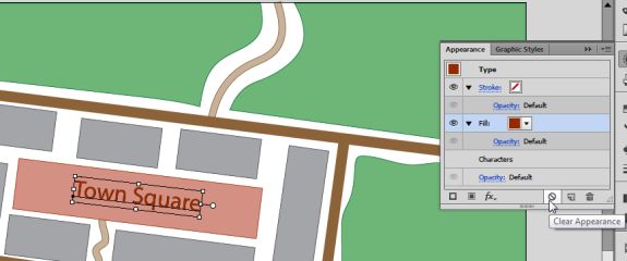
The easiest method to fix this is to use the Clear appearance button in the Appearance panel. Keep in mind that this will totally remove any appearance formatting that you have applied to your layers or objects, so it is worth creating Graphic Styles of the appearances you want to retain. Just like changing appearances, this button works at both the object and layer levels.

The Clear appearance button is a useful way to remove appearance properties.

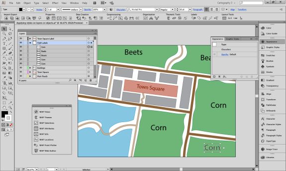
An example of how layer and object appearances can get confused is multiple white strokes applied to different text objects in different ways. The user has created several text objects labelling fields and added strokes to them in various different ways. However, he’d like to remove the strokes from all the text now. You can see that the different labels all have black fills and white strokes, but are subtly different.

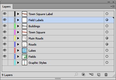
The first thing to do is check the Layers panel. We can see that the target indicator for the Field Labels layer is raised. This indicates that an appearance has been applied to this layer.

The embossed circle (or meatball) shows an appearance has been added.

Once we click on this we can use the Appearance panel to remove it with the “Clear Appearance” button.

The Clear appearance button is a useful way to remove appearance properties.

That has removed the stroke from the layer and one of the text objects now has no stroke, but some of them still do.

The layer strokes have been removed.

If you expand the Field Labels layer in the layers panel you will see that some of the objects on the layer also have appearances applied directly to them.

Some of the text objects have modified appearances.

You can select these objects and use the Appearance panel to remove its strokes as well by clicking the Clear Appearance button.

Clicking on the clear appearance button will remove the stroke.

This leaves us with one final label down in the bottom right corner that still has a stroke, but has not had its appearance modified via the Appearance panel.

Some of the text objects have modified appearances.

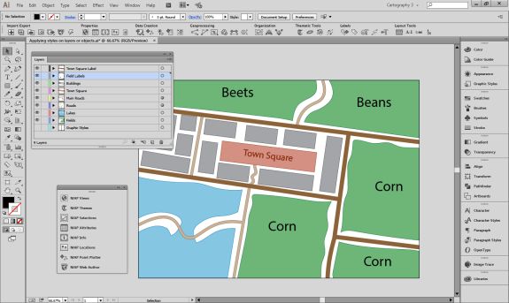
The easiest way to remove the stroke from this object is just to make sure the stroke is in front of the fill at the bottom of the main toolbar and click on the “None” option. Now all our field labels have a simple style.

All of the text objects have a simple appearance.

How MAPublisher works

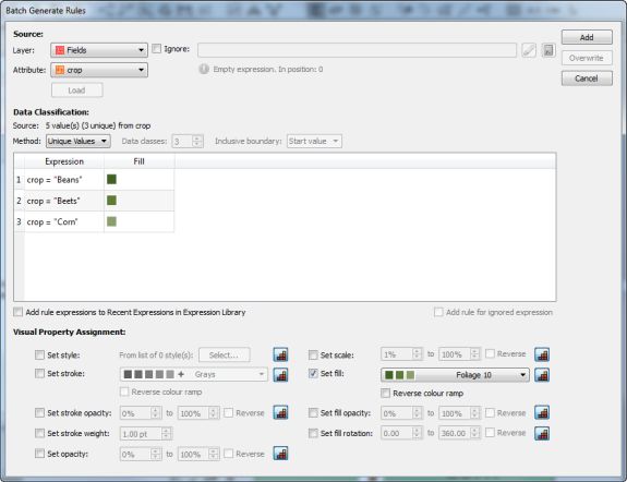
MAPublisher styling tools all work on an object level. This is because MAPublisher has the ability to independently style objects by attributes they possess. For example you can create a new MAP Theme for the Fields layer based on an attribute called “crop”. This will style each field differently using depending upon its crop type.

Area Stylesheet theme.

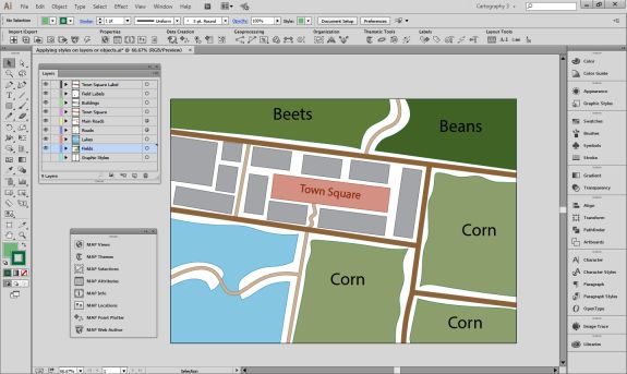
Objects will be styled using standard fills and strokes, rather than using the Appearance panel.

Applied theme.

Using MAPublisher FME Auto to Load Raster Layers into Adobe Illustrator

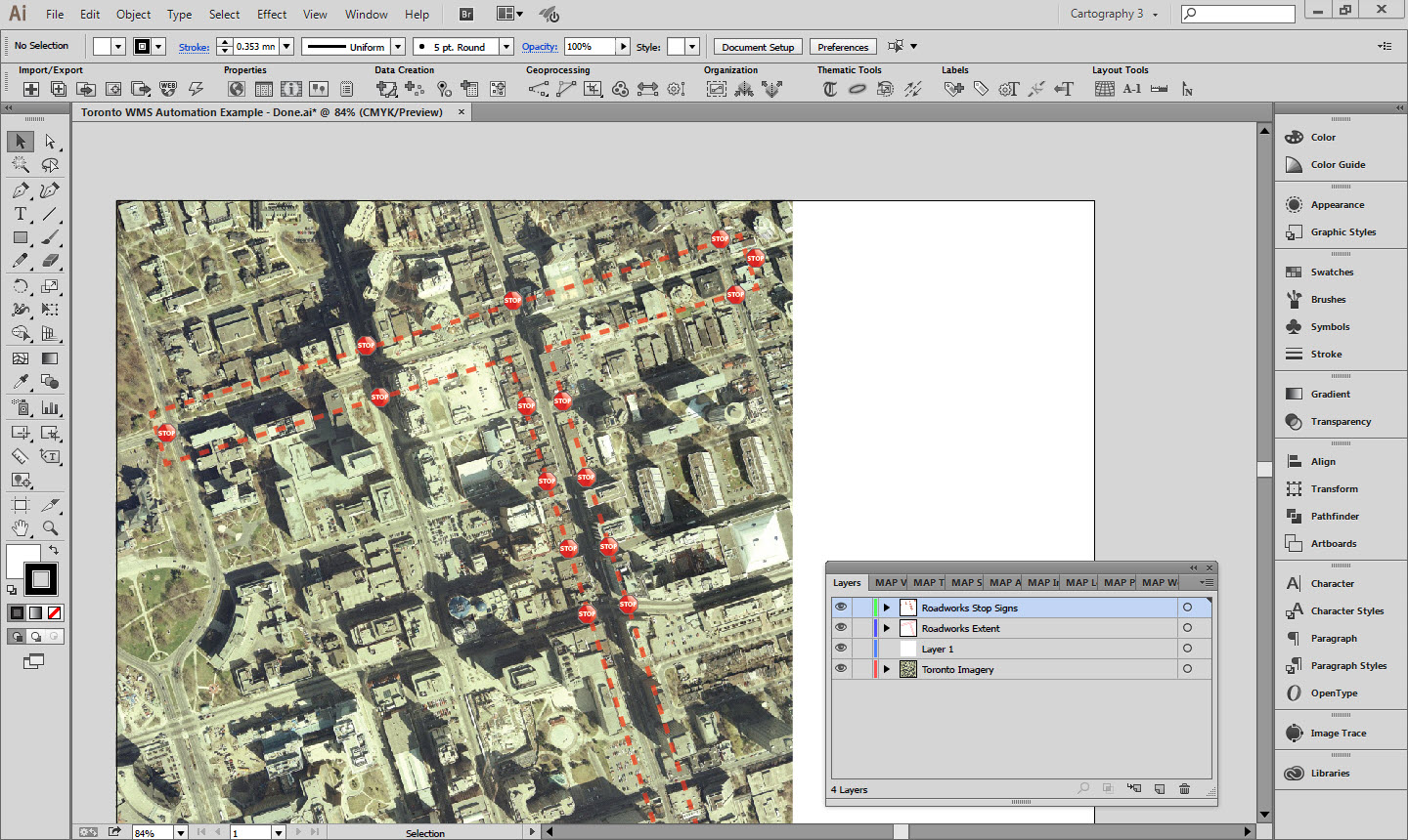
The MAPublisher FME Auto add-on connects the analysis and processing capabilities of Safe Software’s FME Desktop with the cartographic design and publishing environment of MAPublisherand Adobe Illustrator. Since MAPublisher 9.5, it has been possible to import georeferenced raster layers as well as vector data. This adds an extra layer of power and convenience to the FME and MAPublisher integration. The ETL (Extract, Transform, Load) power of FME can be used to pre-process raster images and load them into MAPublisher where they can be overlaid with cartographically styled vector layers.

Raster Layer in Adobe Illustrator

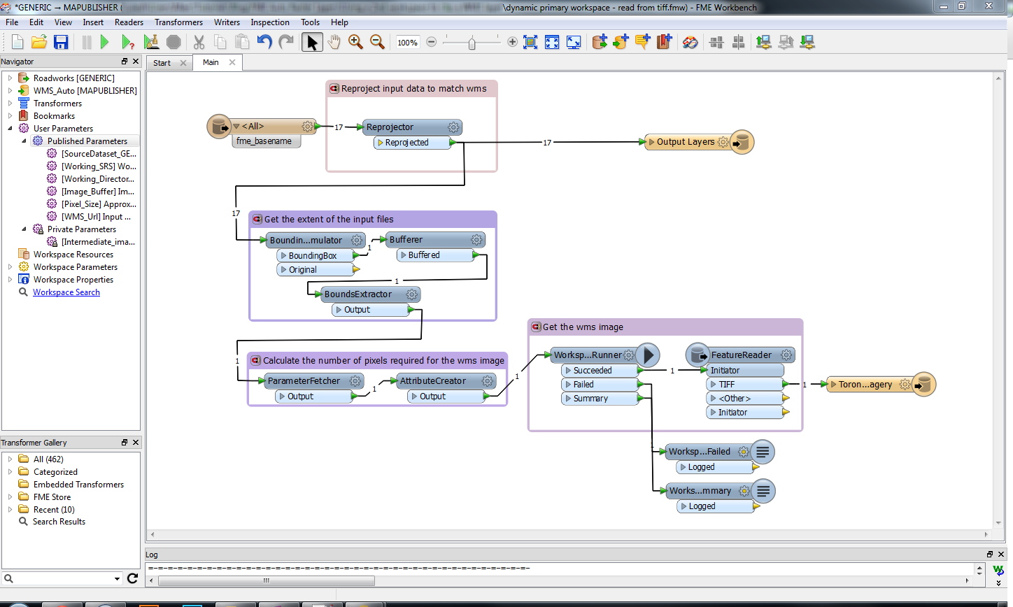
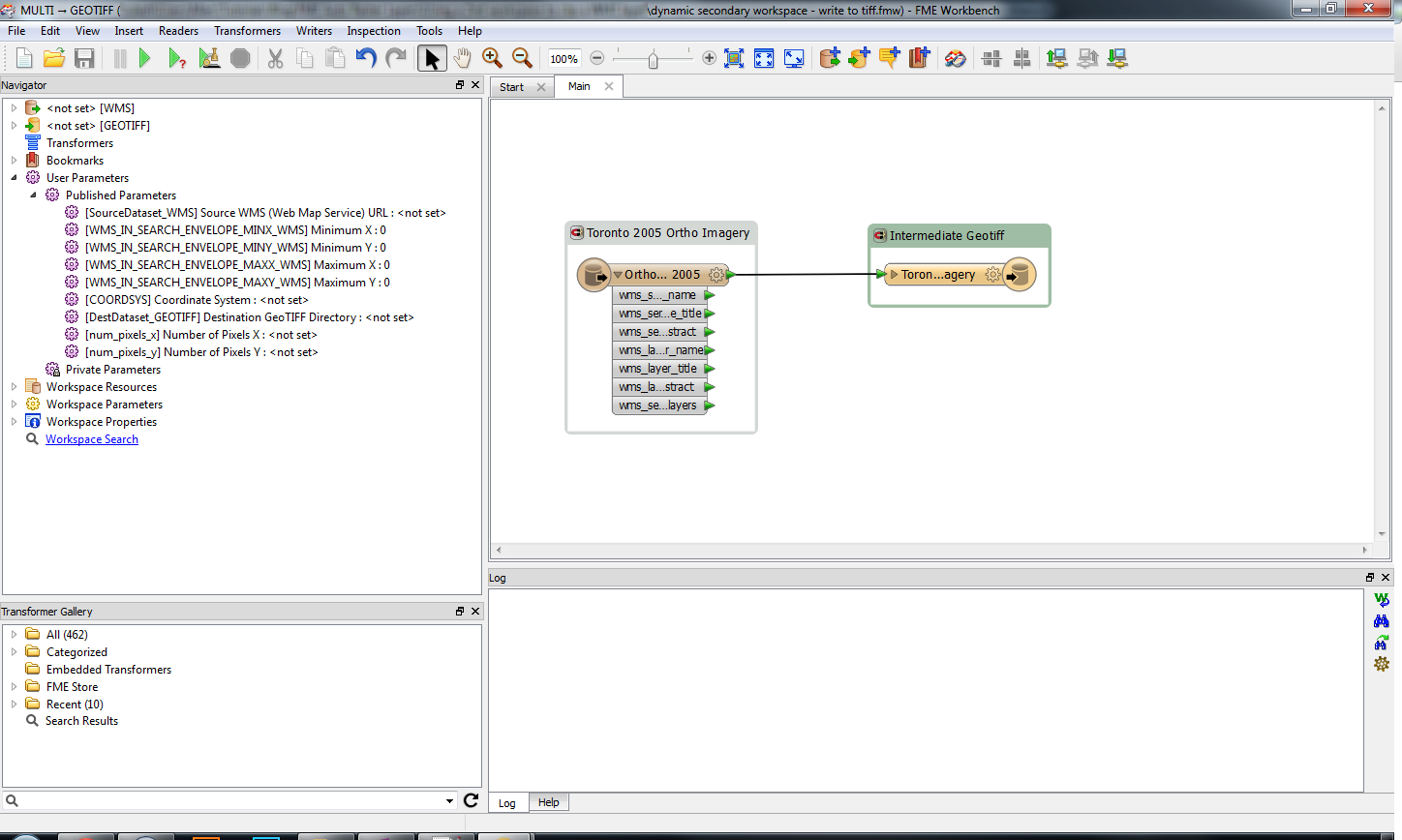
Several components are needed to load a raster from FME into Adobe Illustrator. This example uses a generic reader for the input features. It then gets the bounding box coordinates and sends them to a second workspace that connects to a Web Map Service (WMS) and downloads Toronto imagery. The information necessary to run the second workspace is stored as attributes that are passed to published parameters in the second workspace. This imagery is stored in an intermediate GeoTIFF, which is then read by the first workspace and sent to the MAPublisher writer along with the original data. The WMS source and working coordinate system are already set, but can be modified if the study area is in a different location.

Primary FME Workspace

Secondary FME Workspace

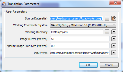
Several of the key parameters for executing the workspace are exposed as published parameters to make running the workspace easier. The user can set the desired pixel size and the pixel dimensions for the WMS request are automatically calculated. The bounding box can be buffered if required to provide extra imagery around the input data.

Published Parameters

MAPublisher MAP Themes are stored in an Adobe Illustrator file that the MAPublisher writer uses as a template. In this case, these MAP Themes are linked to the names of the layers stored in the input data. More flexible themes could be created that bases its symbology on geometry or attribute values.

The example FME workspaces, input data and template illustrator document are attached below in the useful resources section.


Useful Resources

WMS provided by the City of Toronto here
Primary FME Workspace: Download
Secondary FME Workspace: Download
Input Data: Download
Template Illustrator Document: Download
Example completed Illustrator Document: Download

Improve Mosaic By Resampling Images in Geographic Imager

The Mosaic function in Geographic Imager merges multiple georeferenced images together to create a single composite georeferenced image. Though the goal of the mosaic is to create a single and seamless composite image, combining images with the Mosaic tool will often result in a slight shift of the imagery due to differences in the original pixel registration grid. This means that even when images are in the same coordinate system with the same spatial resolution, error can still be introduced because of a difference in the pixel alignment. Due to this, mosaicking processes in general tend to produce results that may be very close, but not exact. With this in mind, the results of your mosaic may be improved by resampling your images beforehand to the smallest unit of the resolution.

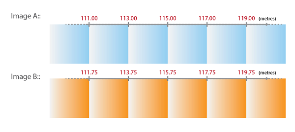
As an example, let’s say we have an image where the pixel size is 2.00 metres. When plotting the X coordinates of every pixel in this image (using the top left corner of the pixel), the X coordinate value will be incremented by the number/distance of the pixel size. For example, if the X coordinate values were to start at 111.00, then the next pixel would be 113.00, 115.00, 117.00, and so on. It’s important to note that these coordinate values are discrete, which means that the values could not be 113.22 or 115.77 because the origin of the coordinate in this case starts at 111.00 metres.

Now, we have another image that we want to mosaic with the first image. In this instance, the first image will be “Image A” and the second image will be “Image B”. Image B has the same coordinate system as well as the same pixel size as Image A.

Take a look at the X coordinates in Image A and Image B below:

We can see that the X coordinate in the top-left corner is different between these two images, and as previously mentioned, we know that the X coordinate values are discrete. When mosaicking Image B to Image A, the X coordinate cannot be 111.75 or 113.75. The coordinates must be 111.00, 113.00, 115.00, and so on, following the pattern of the pixel grid values in Image A.

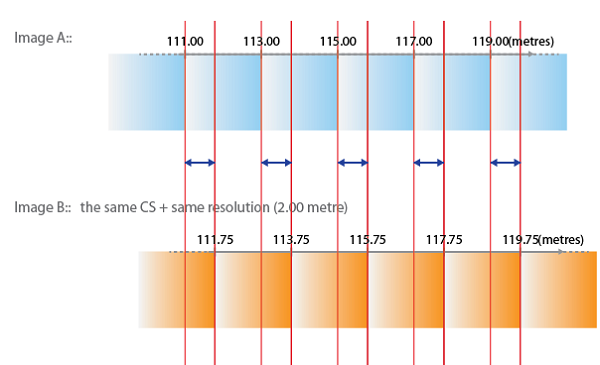
This means that Image B will need to be “shifted” or “snapped” to the closest coordinates when the mosaic is performed, see below:

As a result, the X coordinate of Image B will be shifted by 0.75 metres (less than half a pixel). The pixel with X coordinate 111.75 is now placed at 111.00 and the next pixel with X coordinate of 113.75 will now be placed at 113.00, and so on.

With this in mind, the results of your mosaic may be improved by resampling your images to the “smallest unit of the resolution”. The smallest unit of the resolution can be determined from the difference in the coordinates (spatial alignment difference) between the two images.

Looking back at our example, we can see that the smallest unit of the resolution (represented by the blue arrow) in this case is 0.75 metres – this is the value we will use to resample our images.

Once the images have been resampled to 0.75 metres, we may go ahead with our mosaic.

The above example demonstrates the possibility of a pixel shift after a mosaic for two images with a different pixel alignment. It should be noted that this example explains the problem in one-dimension (looking at only the X coordinate) when the image in reality is in two-dimension (looking at both X and Y coordinates). The basic principal of the pixel shift in 2D is the same, but it would include the direction of the shift when mosaicking images. In addition, it’s important to keep in mind that although resampling your images to the smallest unit of the resolution will improve the final mosaic, this is not always an efficient process when mosaicking with more than two images. Another thing to remember is that resampling your images will make your file size much larger. However, in cases where high precision is desired, resampling the images beforehand is a process that should be considered.

New Image Data Type Available in MAPublisher

Do you have pictures and images you want to insert as an attribute in MAPublisher?

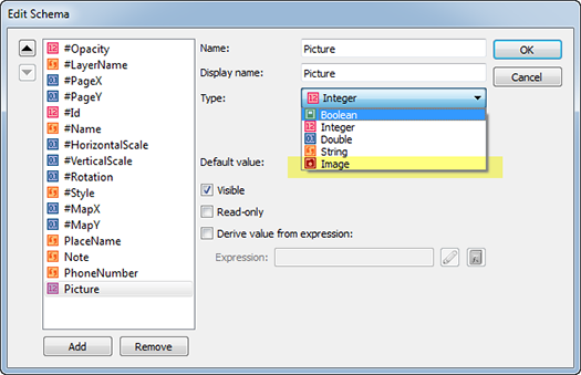
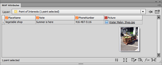
MAPublisher 9.4 introduces a new data type called Image. To work with the Image data type, you’ll have to take a look in the MAP Attributes panel. The Image data type can be used in the same way as the other data types in the MAP Attributes panel. Use the Edit Schema dialog box to edit or create the Image data type as an attribute.

For this example, we have a point layer called “Point of Interests”. Let’s create a new attribute column with Image data type called “Picture”.

Edit Schema with a new data type "Image Data Type

We added a fourth attribute to this point layer (existing attributes were PlaceName, Note, and PhoneNumber).

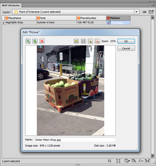
Let’s insert an image into the attribute cell. Click the “No image…” hyperlink in the attribute cell. It will open the Edit Picture dialog box. Click Let's insert an image file to an attribute cell to browse for an image to add to the attribute cell. Once the image is added, a preview of the image will be visible in the Edit Picture dialog box.

Inserting a photo as an attribute value

There are other controls in this dialog box.

Edit Image Attribute Window: button for Select an image Select and insert an image to the attribute cell. Use this button to replace the existing image to something else. You can insert jpg or png file.
Edit Image Attribute Window: button for Export image attribute as jpg or png Export image as jpg or png
Edit Image Attribute Window: button for removing image from the attribute cell Remove image from the attribute cell
Edit Image Attribute Window: button for navigation control (zoom to fit) Navigation control – zoom to fit
Edit Image Attribute Window: button for navigation control (zoom to actual size) Navigation control – zoom to actual size
Edit Image Attribute Window: button for navigation control (zoom in) Navigation control – zoom in
Edit Image Attribute Window: button for navigation control (zoom out) Navigation control – zoom out
Edit Image Attribute Window: Textbox to change the name of the imageChange the name of the image


After clicking OK, the image will be listed in the attribute cell. The cell shows the file name of the image (it will be the file name of the image by default but you can change the name of the image to anything else). Also, hovering the mouse pointer over the image name in the attribute cell will show a quick preview of it.

An image file is inserted to an attribute cell as image data

The Image attribute type also supports images exported from PDF Maps (in KML format) and images exported to Google (in KML format).


Creating a Super Overlay in Google Earth Pro

Our friends in the map library at Brock University in St. Catherines, Ontario have put together a very nice how-to on creating super overlays for Google Earth using Geographic Imager and Adobe Photoshop.

These instructions describe the process of georeferencing a high-resolution image, creating a geotiff file, using Google Earth Pro to make a super overlay and how to provide access to others. The full process is outlined here https://www.brocku.ca/maplibrary/Instruction/Creating_a_super_overlay.pdf

The Brock University Map Library can be contacted at maplib@brocku.ca

3D Terrain Model using Geographic Imager

PLEASE NOTE: As of Photoshop 22.5, Adobe has discontinued support for the program’s 3D features. This may affect some or all elements of this blog. For more information, see Adobe’s FAQ page about this change and the Geographic Imager compatibility information page.

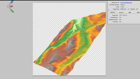
We created a video to show that it is possible to use geospatial data and the 3D capabilities of Adobe Photoshop. It performs very well with a decent computer and video card.

In this video, a combination of Geographic Imager and Adobe Photoshop functions are used to open a DEM file using a script. The script also transforms a DEM into a 3D model and allows for an overlay of a colour model based on the data or a custom image (e.g. ortho image). Video after the jump.

https://youtube.com/watch?v=RgKmJRJUG4M

New in MAPublisher 8.4: Import Map Data from Web Services

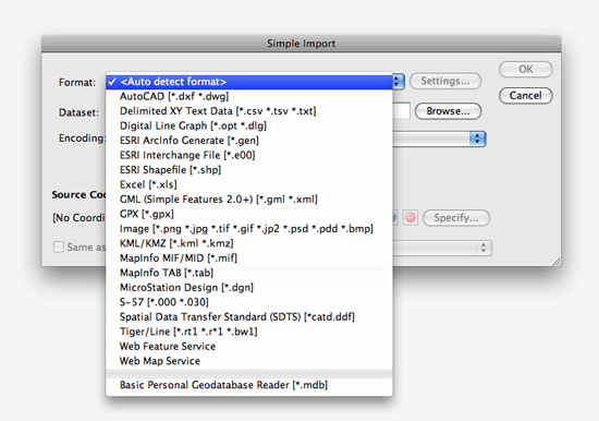
MAPublisher 8.4 has an exciting new feature: importing data from web services. It is another enhancement to provide you with more options to access data.

simple import web service

You can import vector data using the Web Feature Service (WFS). It accesses web servers that deliver vector content in GML format. Similarly, you can import raster data with the Web Map Service (WMS). It accesses web servers that deliver raster content in a variety of formats.

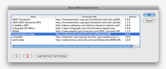
Access the WFS and WMS directly from the Simple or Advanced Import dialog boxes. After selecting either Web Feature Service or Web Map Service from the Format drop-down list, browse for a web service and select one. Of course, you can easily add, remove and manage your favourite WFS/WMS in this dialog box.

WFS Services

After selecting and connecting to a WFS/WMS, simply select features (layers) or rasters you want to import into Adobe Illustrator. At the same time, you will have an option whether or not to save the original datasets in GML format.

WFS Services

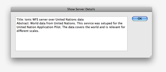
Click the Info button available next to the Server Info at the top of the dialog box. You can see more detail information about the web server.

The server information

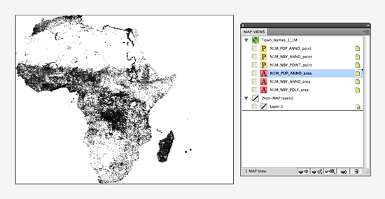
After importing features from the WFS/WMS, each of the features will be in a MAP layer and all the georeferencing of those selected features will be stored in the MAP View.

Imported features from Web Feature Service

Georeferencing an Image in Adobe Photoshop with Geographic Imager

Today's topic: making an image georeferenced

As of Geographic Imager 5.0, there’s an updated workflow for georeferencing images. Learn more about Georeferencing and work through the tutorial.


Nowadays, it’s common to find great orthophotos and satellite imagery on the Web. However, after downloading these (sometimes) large files, you might find that some don’t have any georeferencing. Most likely these files are in an image format supported by Adobe Photoshop(e.g. JPG or TIF) and you can georeference it using the Geographic Imager Georeference tool.

These are the requirements to georeference an image:

  1. Knowing the coordinate system of the image (e.g. Mercator projection, State Plane system Alabama East, UTM system NAD 83 Zone 17 N..etc)
  2. Finding three or more points from the image to assign coordinate values to each of them. These points are known as ground control points.

The first thing you need to know is the coordinate system or projection of the image you are georereferncing. If you are unsure about which coordinate system the image uses, contact the data provider or search the metadata of the image on the Internet. If you cannot get the information of the coordinate system assigned to the image, you might want to try georeferencing with different coordinate systems to make the map as precise as possible.

The second requirement is working with the ground control points. One ground control point consists of several values: 1) Pixel X coordinate, 2) Pixel Y coordinate, 3) Ground X coordinate (e.g. longitude), and 4) Ground Y coordinate (e.g. latitude). Furthermore, to make georeferencing easier, ground control points must be clearly identifiable in the image. Cultural features such as road intersection, a sharp corner of a lot or boundary are good examples of locations used as ground control points.

Now that you know what you’ll need, we’ll demonstrate a georeference workflow using the Geographic Imager Georeference tool and Google Earth.

Step 1: Obtain a non-georeferenced image

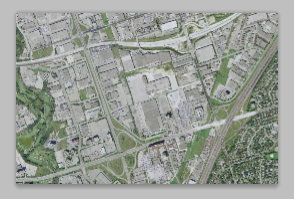
This image is in JPEG format and there is no georeference information associated with it. In order to transform it to another coordinate system or projection, mosaic with other images, or align the image to vector work using MAPublisher for Adobe Illustrator, the image must first be georeferenced.

An example image collected

Step 2: Obtain the required information

As indicated above, two key pieces of information are required to georeference an image: a) the coordinate system of the image and b) defining ground control points

a) The coordinate system of the image

The image, collected from Google Earth, is projected in a coordinate system called WGS84 / Pseudo Mercator (this projection is common to Web based mapping systems and is also known as Web Mercator or Google projection).

b) Defining ground control points

We’ll need to define at least three ground control points for georeferencing. Below are the steps for finding out one of the ground control points.

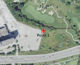
On the non-georeferenced image, decide which spot to use as a point of reference. It should be available on Google Earth where you’ll find the X,Y coordinate values. For the first point, we’ll use the corner boundary between the pavement and a golf course.

a ground control point selected on my image

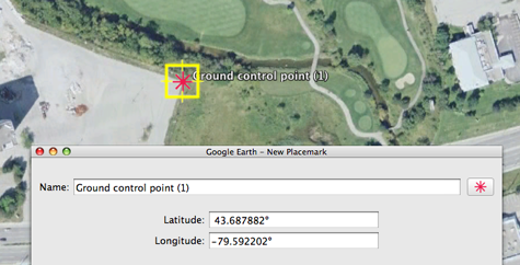
Using Google Earth, find the exact same spot as the one decided in the non-georeferenced image. Place a point symbol to help identify the coordinate values. Record the collected latitude and longitude values. The latitude and longitude values are at the centre of the point symbol symbol in the Google Earth window.

collecting the latitude and longitude values from Google Earth

Find the coordinates of two additional ground control points. The latitude and longitude values are in decimal degree format and the coordinate system of those values are in the geodetic system “WGS84”.

collected three ground control points

Step 3: Georeference in Geographic Imager

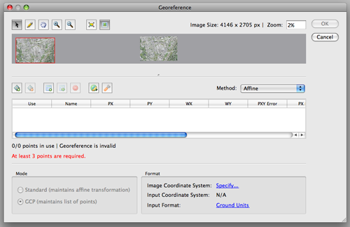
In Geographic Imager, click the Georeference tool button Geographic Imager: Georeference in the Geograhpic Imager main panel (or choose File > Automate > Geographic Imager : Georerence). The Georeference dialog box will open.

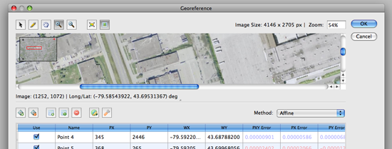
Geographic Imager: Georeference window

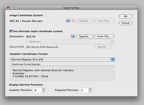
First, we’ll need to set the proper image coordinate system and input coordinate system (the information from Step 2a). In the Format section, click the blue “Specify” link to open the Input Format dialog box.

Georeference: Input

Here we’ll specify two parameters: Image Coordinate System and alternate input coordinate system. The image of the coordinate system is WGS84 / Pseudo-Mercator as found at Step 2a. Click the “Specify” button to find the coordinate system from the coordinate systems list.

The option “Use alternate input coordinate system” will not have to be selected if the X,Y coordinate values are collected in the Eastings/Northings in the WGS84 / Pseudo-Mercator coordinate system. When those latitude and longitude values are collected, those values are collected in the decimal degree format and the values are in degree in WGS84. We will use those latitude and longitude values for the georeferencing. Specify the destination coordinate system as WGS84.

When the settings are made, click OK to close the Input Format dialog box. All the selected coordinate system for each setting will be indicated in the Format section of the Georeference dialog box.

Georeference : Input image coordinate system and input coordinate system

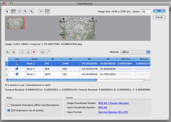
The next step is to enter the three ground control points collected from Google Earth. Click the pencil tool at the top of the Georeference dialog box and click a point for one of the ground control points collected at the previous steps Georeference : Pencil tool.

a ground control point selected on my image

As soon as one point is clicked on the preview image, it will add one row in the Georeference table. This row contains the point name, PX (Pixel x coordinate), PY (Pixel y coordinate), WX (World X coordinate), and WY (World Y coordinate).

Ground control point 1

For WX and WY, enter the longitude and latitude, respectively, for the first ground control point.

ground control 1: completed

Repeat the same steps for the second and third ground control points.

All three ground control points are entered

As soon as you enter three points, Geographic Imager will display the residual error values on the table for the accuracy assessment.

GCP Error

A residual error is the computed difference between an observed source coordinate and a calculated source coordinate. It is the measure of the fit between the true locations and the transformed locations of the output control points. A high residual error indicates possible error in either the observed source coordinates or the reference coordinates of the reference point in question.

When the error is particularly large, you may want to remove and add control points to adjust the error. As a general rule, apply several different transformation methods, select/deselect questionable points and select the method and reference points that yield the minimum residual error, assuming that the defined reference points are correct. Residual values are calculated via the associated error values between computed values and entered values through either the affine or various polynomial methods.

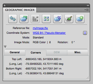
Once completed, the Geographic Imager main panel will indicate the georeference information of the image. Don’t forget to save the file once it is complete. Now your image is ready for any Geographic Imager function. You can also bring this image into MAPublisher for Adobe illustrator and align it to other GIS data.

Georeference information displayed on the Geographic Imager Main panel

New in MAPublisher 8.4: Image MAP Layer feature type for georeferenced images

MAPublisher 8.4 introduces two new related features: to import supported image formats directly from the MAPublisher Simple and Advanced Import dialog boxes and the Image MAP Layer feature type. To import a georeferenced image into the current MAPublisher 8.3 (and earlier) requires you 1) to create a new MAP Layer for an image to be placed, 2) use File > Place to place an image into the Adobe Illustrator document, and 3) to use MAPublisher Register Image to align with the vector work. With MAPublisher 8.4, these steps are streamlined and it will be much simpler to deal with georeferenced image files.

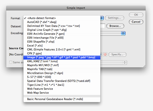
Below is the Simple Import dialog box. The new Format option, Image, is added to the drop-down list. Supported images include: PNG, JPG, TIF, GIF, JP2, PSD, PDD, and BMP.

MAPublisher 8.4: Import dialog window

The VancouverDowntown.tif file was selected from the MAPublisher Quick Start dataset. The source coordinate system of the image, “NAD 83 / UTM Zone 10N”, is automatically detected because it is a GeoTIFF and contains the georeference information of the image.

MAPublisher Simple Import: Coordinate System identified for the selected data

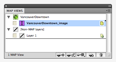
When the georeferenced image is imported by MAPublisher, it is stored in a new layer called “VancouverDowntown_image”. MAPublisher 8.4 introduces a new MAP Layer feature type called “Image”, a purple icon with the letter ” I “. From now on, all images should be placed on Image MAP Layers.

MAPView: New data type "IMAGE"

Remember that images placed in Adobe Illustrator using MAPublisher cannot be transformed or reprojected into another coordinate system. To transform an image from one coordinate system to another, it must be done using another software such as Geographic Imager.

MAPublisher 8.4 will be released very soon. Thanks for sending us feature requests like this one. If you have any feature requests for MAPublisher, Geographic Imager or PDF Maps, please feel free to drop us a line at support@avenza.com. We’re always happy to hear from you!

News Archive