My Account     Contact Us     Cart

Explore all that you can do with the latest ‘Spatial Join’

By Olly Normanton, QA Specialist


This is one feature we have all been waiting for. Spatial Join is a very useful tool to be included in the MAPublisher roster as of version 10.6 and I would like to share a little bit about the tool with you in this feature blog. 

The Spatial Join tool inserts the columns and attributes from one feature table to another based on location or proximity. Currently, we support several Spatial Join types including:

  • Intersects: If any part of two features touch at any location
  • Identical To: Both features match identically
  • Contains: When one feature intersects with the interior or boundary of another
  • Near: If a line can be drawn from any part of A to any part of B that is less than the specified minimum distance
  • Closest: If a line can be drawn from any part of A to any part of B that is less than any other such line between B & any other feature
  • Has Centre In: When one features centroid lies Within another feature
  • Within: If all of one feature lies within the interior boundary of another


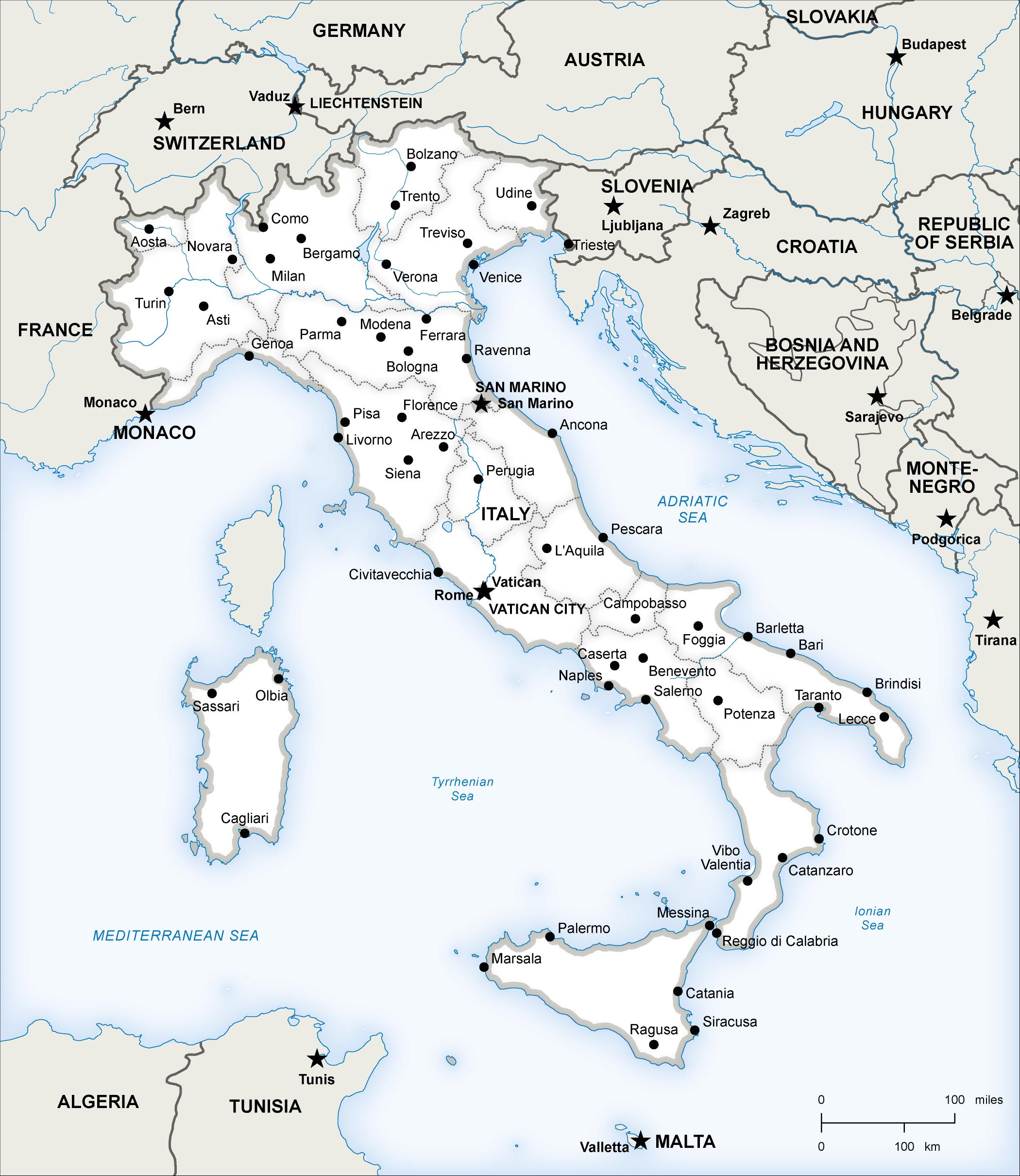
Here is a wonderful map of Italy created by Hans van der Maarel of Red Geographics available through the One Stop Map service. It will provide a great way to show you some examples of the Spatial Join tool in action. It contains a Cities layer and a Regions layer and I would like to see which cities fall into each region by using Spatial Join.

Cities and Region Layer using MAPublisher 10.6

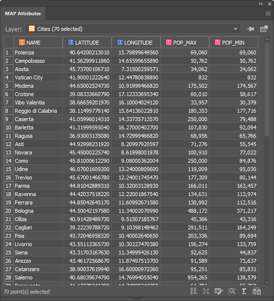
You can see below that the Cities attribute table contains the name of each city and there are 70 in total. 

MAP Attributes on MAPublisher 10.6

There are 20 different regions that these cities lie within. To figure out which cities belong to which region, we have the ability to spatially join attribute information from the Cities point layer to the Regions area layer. In addition, we’ll use the Concatenate operation on the NAME attribute to list all the cities that belong to a region in one field.

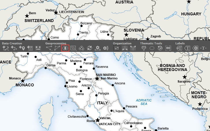
To do this, click the new Spatial Join button on the MAPublisher toolbar or access the Spatial Join dialog box via Object > MAPublisher > Spatial Join. 

Spatial Join Button on MAPublisher 10.6

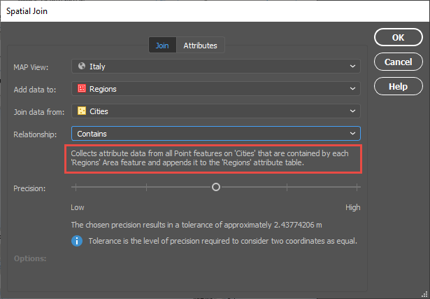
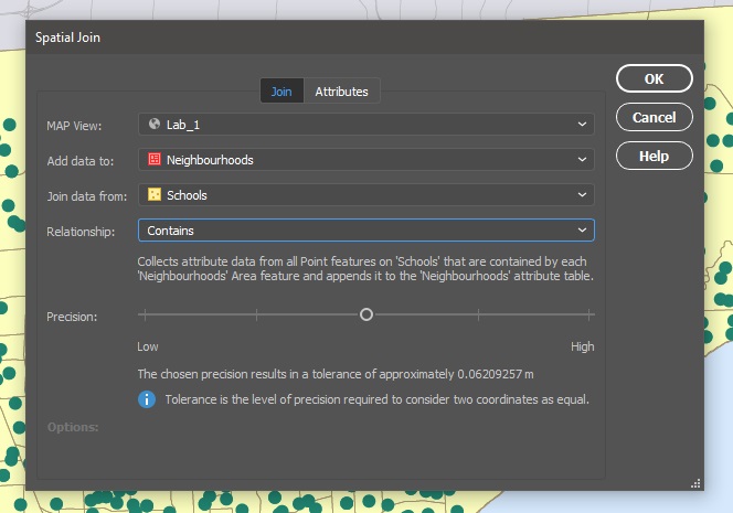
The Spatial Join tool will always open on the Join tab seen below. I will be adding data to my Regions area layer and joining data from my Cities point layer. The relationship is set to Contains—in other words, when one feature intersects with the interior or boundary of another. A description of the operation is always provided beneath the relationship. 

Spatial Join Tool on MAPublisher 10.6

The Precision slider alters the tolerance that is used to determine when two values are equivalent (or approaching equivalent). Depending on your data, this may need to be altered in some cases but for this example, I will be leaving it in the default position. 

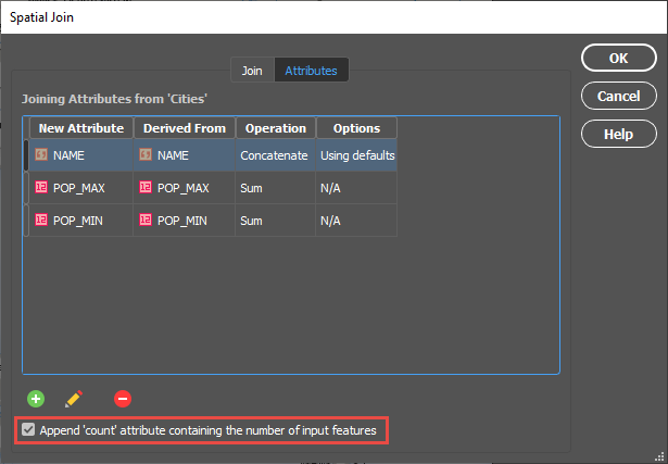
On the Attributes tab, I am going to concatenate the NAME field. By double-clicking on the attribute, I can access the Edit Calculated Attribute Operation dialog box. In addition, I am going to sum both the POP_MAX and POP_MIN attributes. I’m also going to append a Count attribute to the table so I can quickly verify how many cities are in each region.

Spatial Join Tool on MAPublisher 10.6

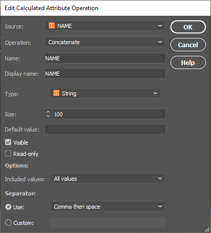
Within the Edit Calculated Attribute Operation dialog box, I am going to set the Operation drop-down to Concatenate and leave the separator as default as Comma then space. 

Spatial Join Tool on MAPublisher 10.6

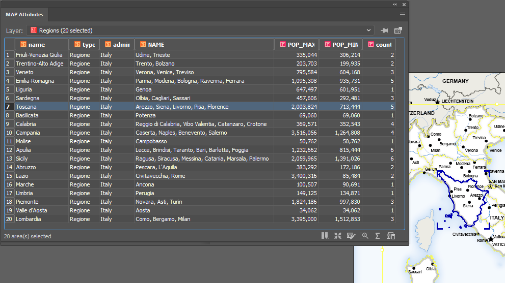
After confirming the Spatial Join with the OK button, we’ll open the MAP Attribute table for the Regions area layer and take a look at the results.

Spatial Join Result

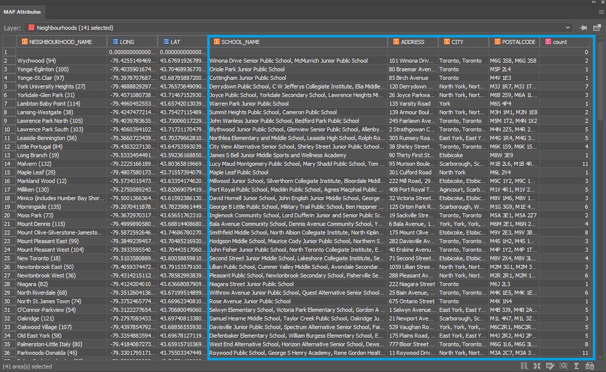
You can see that the cities have been concatenated by region and the POP_MAX and POP_MIN attributes have been summed for the regions based on the cities contained within them. The count attribute was also added to the attribute table and as only 56 of our 70 cities were within the Italian Regions area layer, that is the total value of our count. 
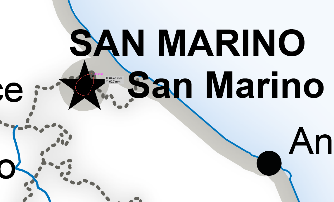
For the eagle-eyed readers who may have noticed that there are only 12 cities that surround Italy in the full map displayed at the beginning of this article and 70 – 56 = 14, the difference can be explained by San Marino and Vatican City, both of which are autonomous countries and not part of Italy. You can see that they are in fact separate polygons. 
City Map

For a full list of the relationships that are available based on the different layer types, and also the input attribute types, please see the tables below. 

Layer Attributes
Input Attribute Table

This post was made using the incredibly beautiful map data provided by our good friends over at One Stop Map. Stay tuned as MAPublisher Aware Maps are coming very soon to the One Stop Map Store, which will allow you to directly purchase the Adobe Illustrator files and put your own style on the maps! If you’re interested in seeing more of their work, take a look at these One Stop Map Country Maps.


Plotting Curved Lines in MAPublisher: It’s Here!

MAPublisher 10.6 has now been released and we are very excited to share these powerful new features with you. If you’re new to MAPublisher, you can get a rundown of the full feature set here, and even try it free for 14 days. In this feature highlight blog, I will be providing a brief overview of the ability to Plot Curved Lines with the Line Plotter tool. 

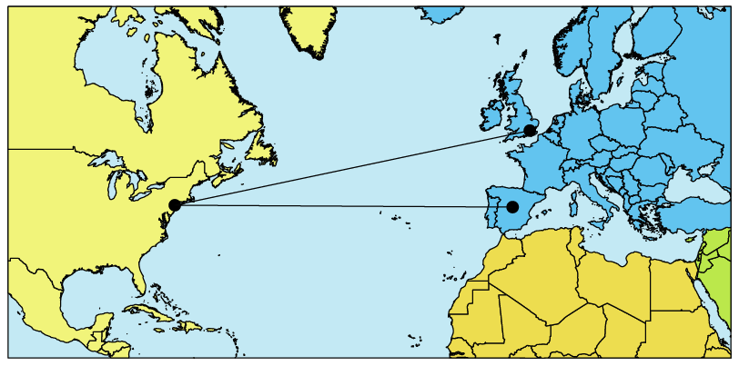
When plotting a line from point to point, you now have the option of selecting whether that line is Geodesic (also known as a Great Circle), Cartesian (planar), or a Rhumb Line (also known as Loxodromic). To provide a brief definition of each type:

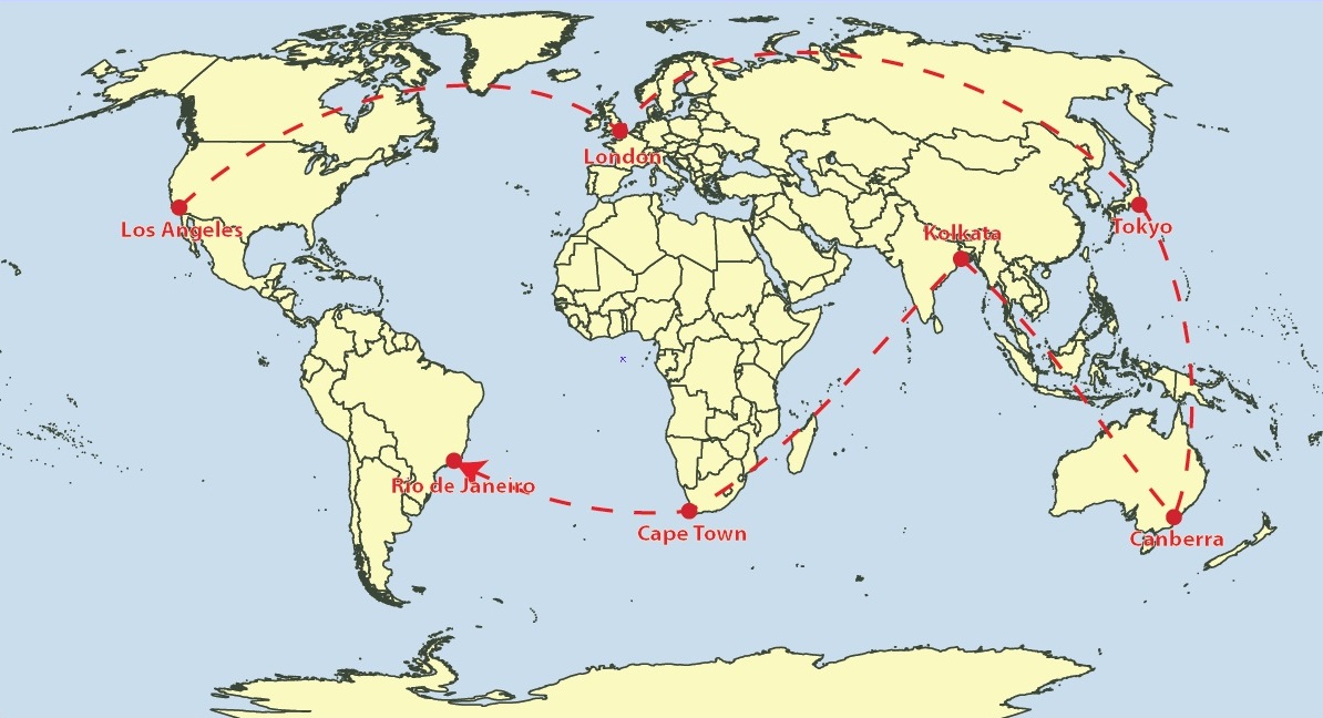
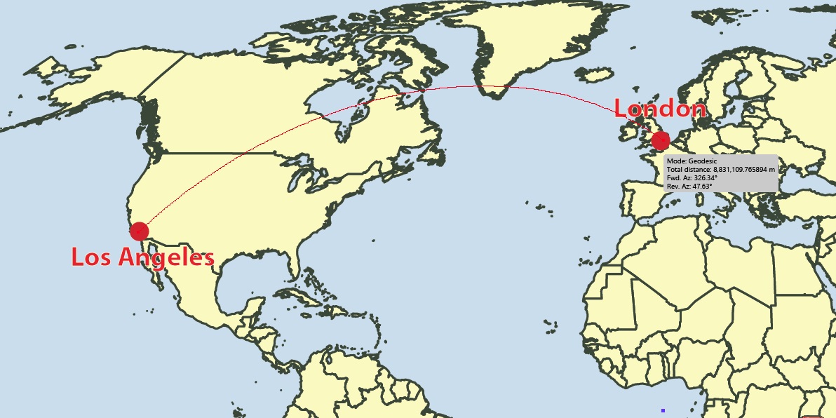
Geodesic line: the shortest line between two points on a mathematically defined surface (as a straight line on a plane or an arc of a great circle on a sphere or ellipsoid like the Earth’s surface). On a geodesic line, the bearing to the destination point does not remain constant. This would be the type of line you would want to use when determining a flight path between two cities, for example. 

Rhumb line: this is a path with constant bearing as measured relative to true or magnetic north and is rarely the shortest line between two points. A rhumb line on a Mercator projection is a straight line which made the projection incredibly useful to navigators from as early as the 16th century.


Rhum Line Mercator - MAPublisher 10.6

Rhumb Lines on a Mercator Projection

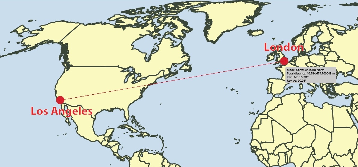
Cartesian line: can simply be defined as a straight line connecting points.

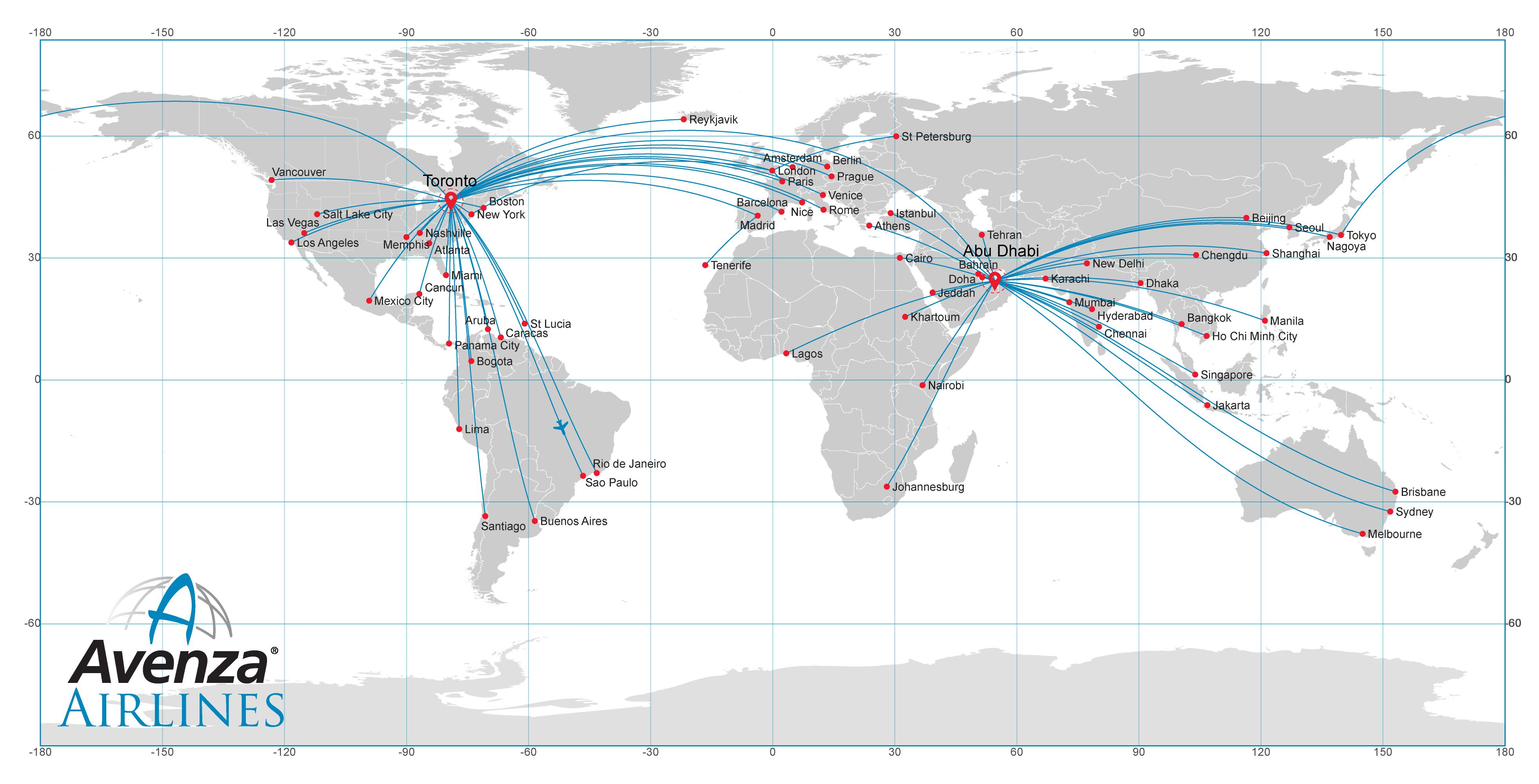
To view this feature in action, we are going to be using curved geodesic lines to create an Airline Route Map. The reason why we are using geodesic lines for this type of map is because they provide the most economical route in terms of distance. Following the rhumb line would waste time and fuel for all but the most brief routes. 

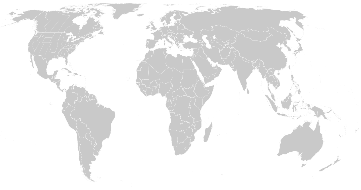
I began by importing some data that provided my backdrop for the routes I am planning to map. My flights will span the entire globe so I required world coverage. You can also test out this feature and use the World.mif file or the WorldEast.shp and WorldWest.shp files provided in the MAPublisher tutorial data. 

I decided to use the Equal Earth Projected coordinate system.

Adding Locations

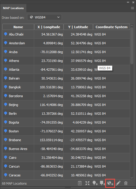
The next step was to establish the hubs from which our aircraft would fly and the destinations that we would offer as an airline company. For this, I needed points and coordinates. Instead of searching for and importing a hefty list of airports and then trying to filter down to ones of interest to me with selections, I opted to use the MAP Locations tool. 

MAP locations - MAPublisher 10.6

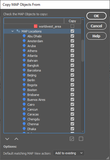
By utilizing the “Add Map Locations from web” feature highlighted at the bottom of the MAP Locations panel, adding each destination and its corresponding coordinates was as easy as typing in the city’s name. It can take a while to establish all of your locations but the best thing is that you only need to do this process once as the MAP Locations can easily be brought to other documents using the Copy MAP Objects From feature.

Copy MAP Objects - MAPublisher 10.6

Plotting Points

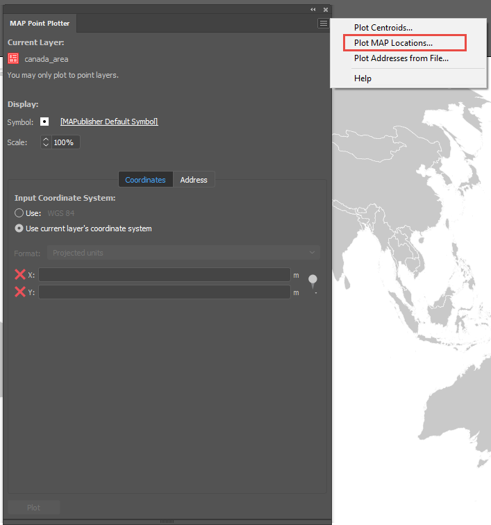
Now that I had all of my locations of interest and their coordinates, I could plot these onto my map as points. For this I used the MAP Point Plotter. 

Plotting Points - MAPublisher 10.6

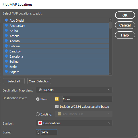
By accessing the panel options menu in the top right-hand corner, you can select Plot MAP Locations. In the dialog that opens, select all of the city MAP Locations. In my example, I selected all and then de-selected Abu Dhabi and Toronto as these will be my main hubs and will be plotted with a different custom symbol to other destinations.

Plot MAP Locations - MAPublisher 10.6

I chose to plot them to a new Point layer that I named “Cities” and I included WGS84 values as attributes. I created a custom red main hub symbol using Adobe Illustrator tools to use for my destinations. You may need to play with the scaling of the symbol to get your desired look. 

Location Symbol on Avenza Maps

To create a custom symbol in Adobe Illustrator, draw out your design like the main hub symbol above, highlight the art, and drag the art to the Symbol window that can be accessed by going to Window > Symbols. You can then give it a name and select the static symbol option. 

Plotting the Routes

With the cities and main hubs now plotted, it was time to add the routes. 

plotting the routes - MAPublisher 10.6

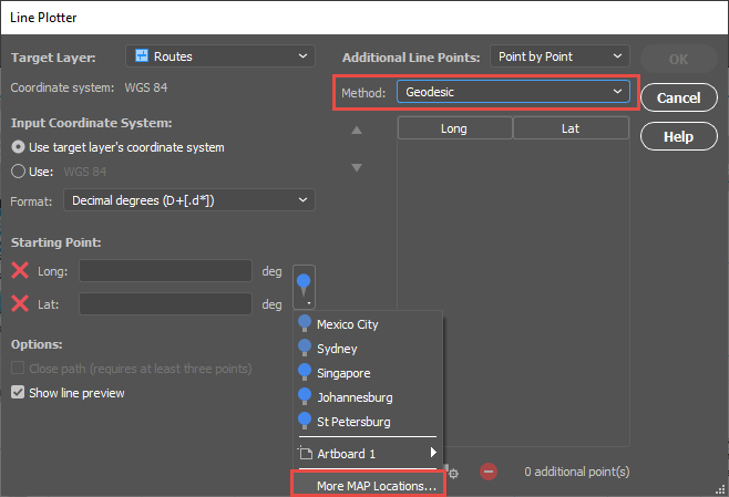
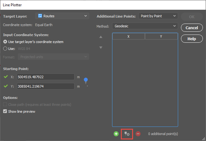
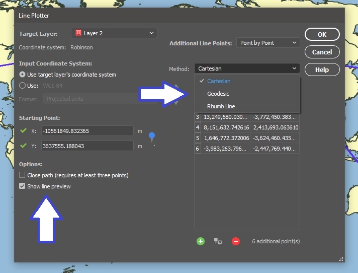
Line Plotter - MAPublisher 10.6

I targeted a new Line layer called “Routes” and set my start point using the MAP Locations selector. I was sure to change the Method to Geodesic. 

Line Plotter - MAPublisher 10.6
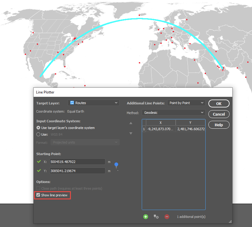
I started adding cities using the “Add Point from MAP Location” control shown here. Once you select your point, a preview will be drawn onto the artboard if your “Show line preview” option is checked.

Line Plotter - MAPublisher 10.6

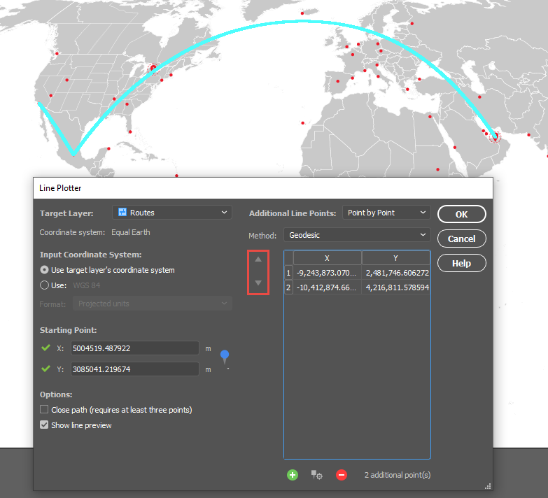
The route above is from Abu Dhabi to Mexico City. You can select multiple destinations to account for layovers. You can also change the order of the points once they are in the list using the arrows highlighted below. 

Line Plotter - MAPublisher 10.6

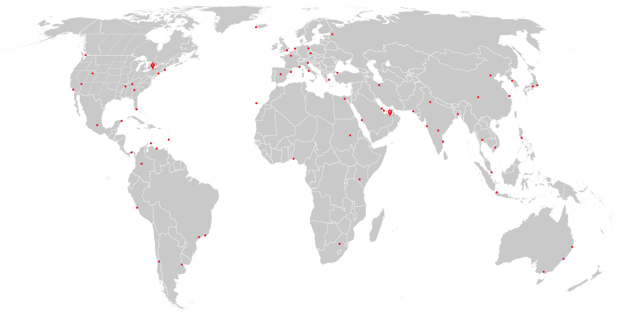
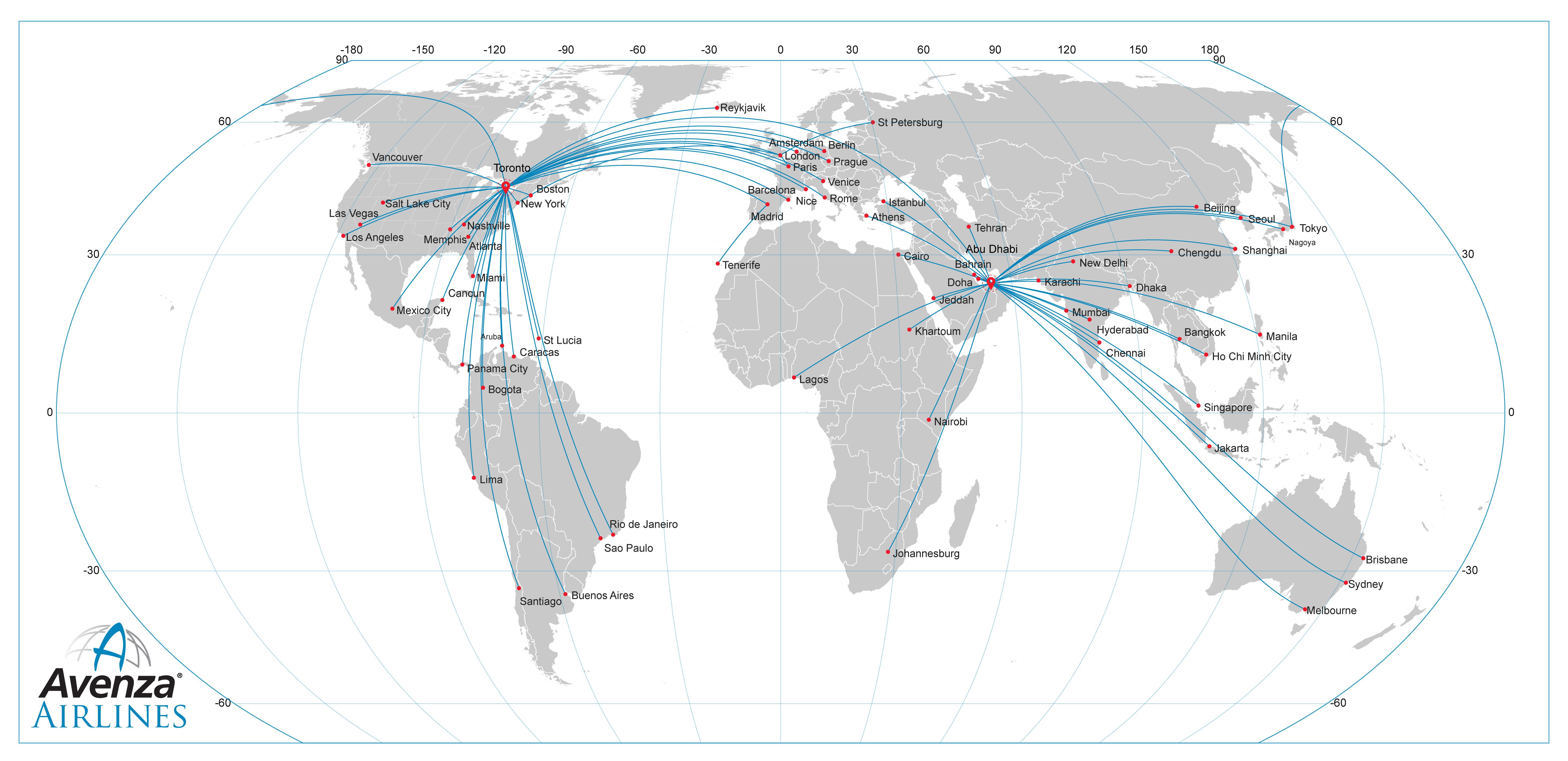
Once all of the routes have been plotted, the points were labelled with MAP Label Pro and a customized graticule was added. Here’s the final map in two projection styles to show how a map projection can change the look of the routes and the overall look of the map.

Airline Route Map - Avenza Systems

Projected Coordinate System: Equal Earth

Geodetic Route Map - Avenza Systems

Geodetic Coordinate System: WGS84

_______________

By Olly Normanton, QA Specialist 

What’s New in MAPublisher 10.6

Continued Compatibility with Adobe 2020

Both Windows (64-bit) and Mac users can explore the exciting new and improved features MAPublisher 10.6 offers with the latest version of Adobe Illustrator. Talk about a power duo — upgrade today (it’s free for maintenance users)!

Spatial Join

In our line of work, spatial relationships are really important and can be complicated, but working with them shouldn’t be. MAPublisher 10.6 delivers the brand-new Spatial Join feature and we’re ecstatic to be sharing it with you. With Spatial Join, you can:

  • copy attributes from one layer to another based on their spatial relationship
  • use relationships including Near, Closest, Identical To, Contains, Within, Has Centre In, and Intersects
  • adjust the Precision and Tolerance


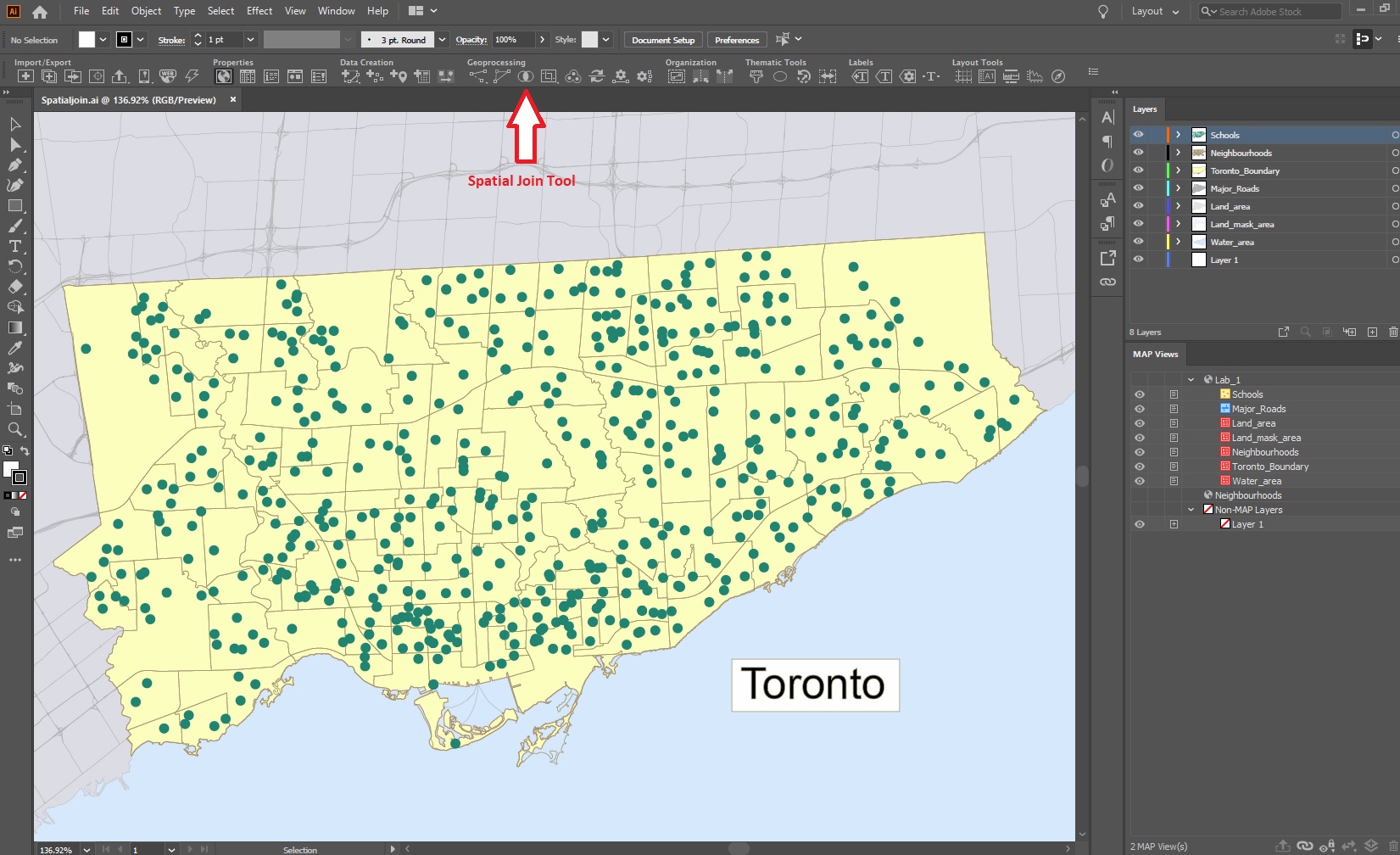
Spatial Join Tool

Spatial Join Tool MAPublisher 10.6

Spatial Join tool

Spatial Join for MAPublisher 10.6

Features joined based on spatial relationship

Improved Line Plotter

The Earth isn’t flat, and your plotted lines shouldn’t be either! The improved Line Plotter tool will accurately plot lines with the Geodesic and Rhumb line methods, taking your projection into consideration (or calculation if we’re getting technical) and is available for both Point by Point and Course & Distance plotting styles.

The Rhumb line method will create either straight or curved lines, depending on the projection used. Still want to plot straight lines? The Cartesian method is sticking around and will work just as you remember it. A preview option is now available, so you can take a look at the three different methods on your map before plotting the line (or simply turn it off if your line has too many points).

Line Plotter Settings MAPublisher 10.6

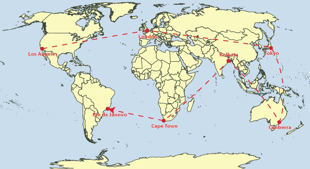
geodesic_lineplotter MAPublisher 10.6

Geodesic Method: Shortest distance between points

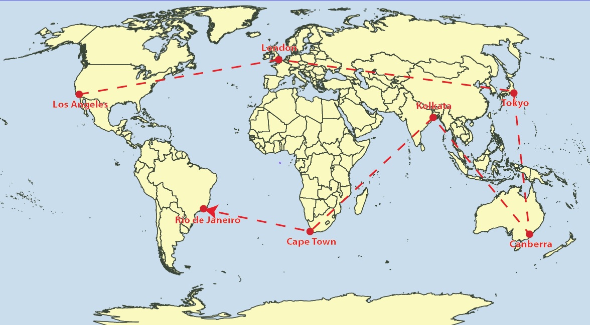
Rhumbline Line Plotter MAPublisher 10.6

Rhumb lines: Constant bearing, curved or straight depending on the map projection.

cartesian_lineplotter MAPublisher 10.6

Cartesian lines: straight lines from destination to destination.

Improved Map Measurement Tool

linemeasurement Settings MAPublisher 10.6


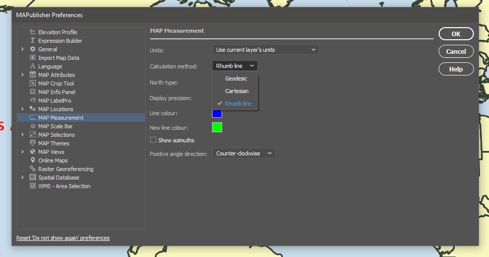
With the addition of the Geodesic and Rhumb methods for plotting lines, we’ve made sure you can accurately measure the distance between points with these methods as well, whether they’re curved or straight lines.

  • Measure distances between points using Geodesic, Cartesian and Rhumb line methods
  • Like the Line Plotter, Geodesic and Rhumb measurement lines can be curved or straight, depending on the map projection
  • A combination of keyboard presses (Shift + Click) will add the measurement line as an object on your layer

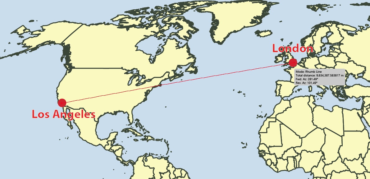
Rhumbline Measurement MAPublisher 10.6

Rhumb Measurement Line

Geodesic Measurement Line MAPublisher 10.6

Geodesic measurement line

cartesian_measurement MAPublisher 10.6

Cartesian Measurement Line

Installer Will Uninstall Previous Versions

We’ve made some improvements to the installer. You’ll notice that the MAPublisher 10.6 installer will prompt you to uninstall previous versions of MAPublisher. We’ve designed the installer to guide you through this process. You can also uninstall older versions through the Control Panel (Windows) or as usually on macOS.

Export Document to Image

Colours on a map can make important information pop or sometimes they just make the map look nice. Whichever way, we’ve made sure your colour profiles stick around when exporting your document to an image. ICC profiles (the data that characterizes a coloured input or output device) will be embedded when documents are exported as TIFF files. If an Adobe Illustrator document is in the CMYK colour space, its colour profile will be embedded in the TIFF if the exported TIFF’s colour mode is also set to CMYK.

Map Data Links

We’ve made it easier to keep your workspace clean. Previously, when a layer is deleted, data links were not removed. In MAPublisher 10.6, data links are now removed when a layer is deleted and is the new default behaviour.

Stay safe out there and happy Spring cleaning!

What’s New? Geographic Imager 6.1

Geographic Imager 6.1 is available now and in addition to full compatibility with Adobe Photoshop 2020, here are the other exciting new features to make working with spatial imagery in Photoshop even easier:

Vector Import from databases

Geographic Imager allows you to import a number of GIS vector formats directly on to your images in Photoshop. Whether performing a check to ensure accurate georeferencing, QA/QC or simply including supplemental data, this functionality allows you to improve the efficiency of your workflow. For a while, it was only possible to import vector data from your own files however we have added the capability to import from databases including PostGIS Spatial Database, and ESRI File and Personal Databases (.gdb and .mdb). Note that importing vector data from databases is only available in the full version of Geographic Imager.

Improved Mosaic Layer organization

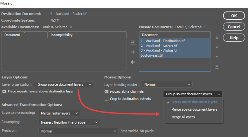
When mosaicking documents in Photoshop with Geographic Imager’s Mosaic tools, you previously had the option to either group the layers from each document into folders or merge all layers into one single layer. In this new release, we’ve added a new option to merge source document layers which will flatten each source document into a single layer, but also keep each document separated in the destination, without the use of folders. This helps to keep the individual images separate while minimizing the number of layers and folders you need to deal with.

Improved mosaic layer

Geographic Imager 6.1 Improved mosaic layer

7 GIS terms To Know: Map Making for Designers

Many of our MAPublisher clients are cartographers and GIS professionals, but a growing number are graphic designers who are tired of the tedious work of making maps without specialized tools. Making a map is part art and part science and while we help bridge the gap between Geographic Information Systems (the science) and graphic design (the art), as a graphic designer, you may not be familiar with the wonderful world of GIS.

So on this GIS Day, we have compiled the definitions to a few common GIS terms that you may encounter; GIS Day, celebrated each year, in November to help educate non-GIS professionals about the importance of geospatial information systems and the benefits that GIS brings to our lives.

1. Spatial Analysis

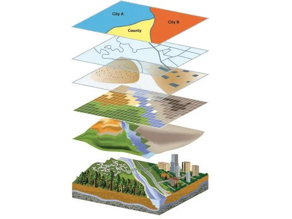
Any good and useful design involves analysis. This process of stacking layers, inspecting and interpreting model results seeks to solve complex location-oriented problems. This can be used for predictive analysis, estimating the level of suitability and for further understanding of the geographic location. 

spatial analysis

2. Layer 

Maps contain several layers, each representing a set of spatial features. Layers are laid atop one another for viewing or spatial analysis. This lends itself to working with the map layers in Illustrator, as they can be treated similarly to a layer containing artwork.  

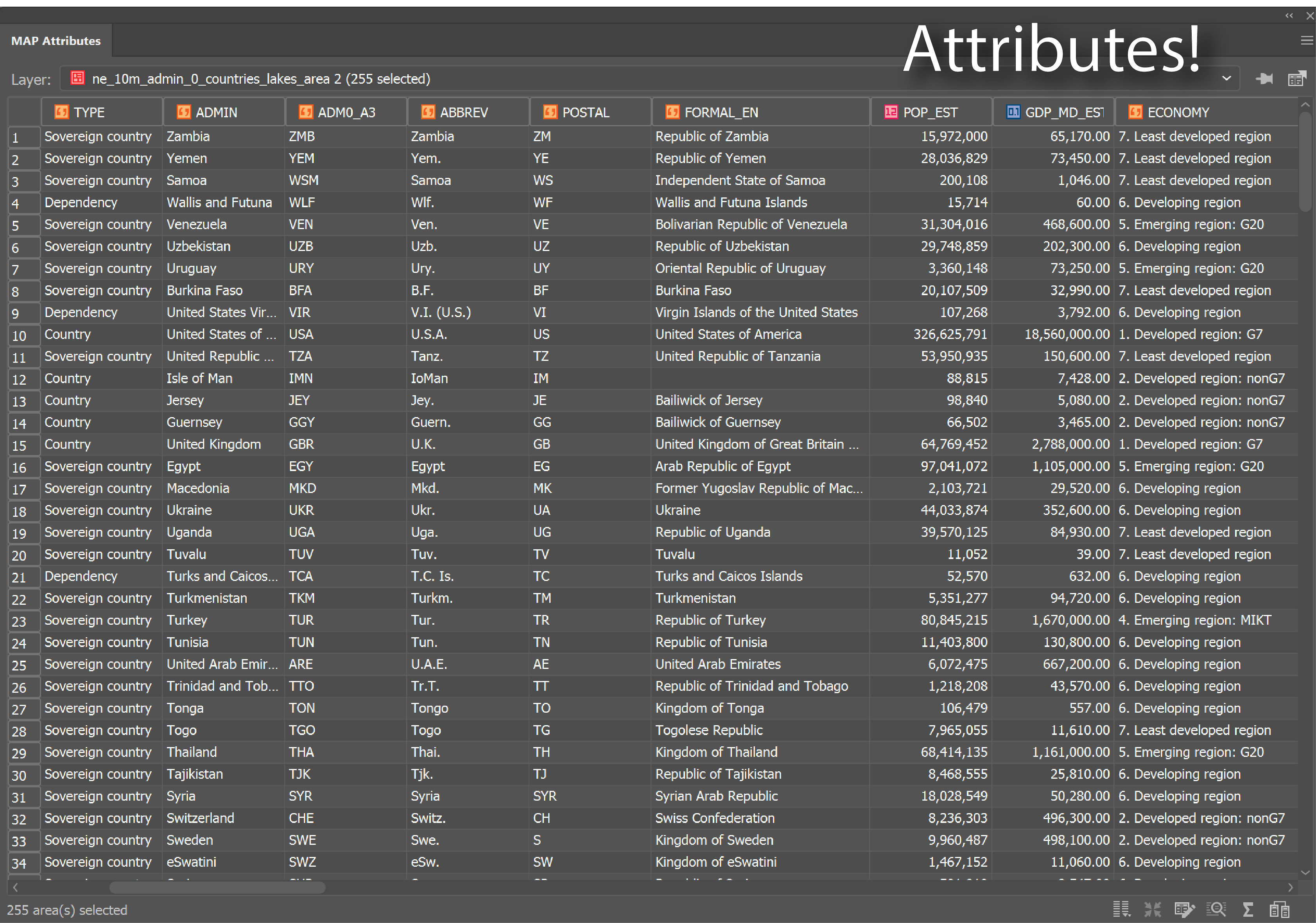
3. Attributes

Attributes denote a geographic feature on a map. The information is typically stored in a tabular format that is linked to the feature. For instance, the attributes of a well-represented point along a river may include the name, the course of the river/ length, sediment load, etc. 

When you are familiar with the attributes associated with the map data, you can do things like applying rules to style your map according to attributes in the table.

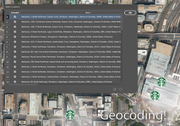
4. Geocoding

Geocoding

The process identifies a location by its geographic coordinates (latitude and longitude). This is used to position places and features on a map as well as to reference the map itself. 

5. Buffers

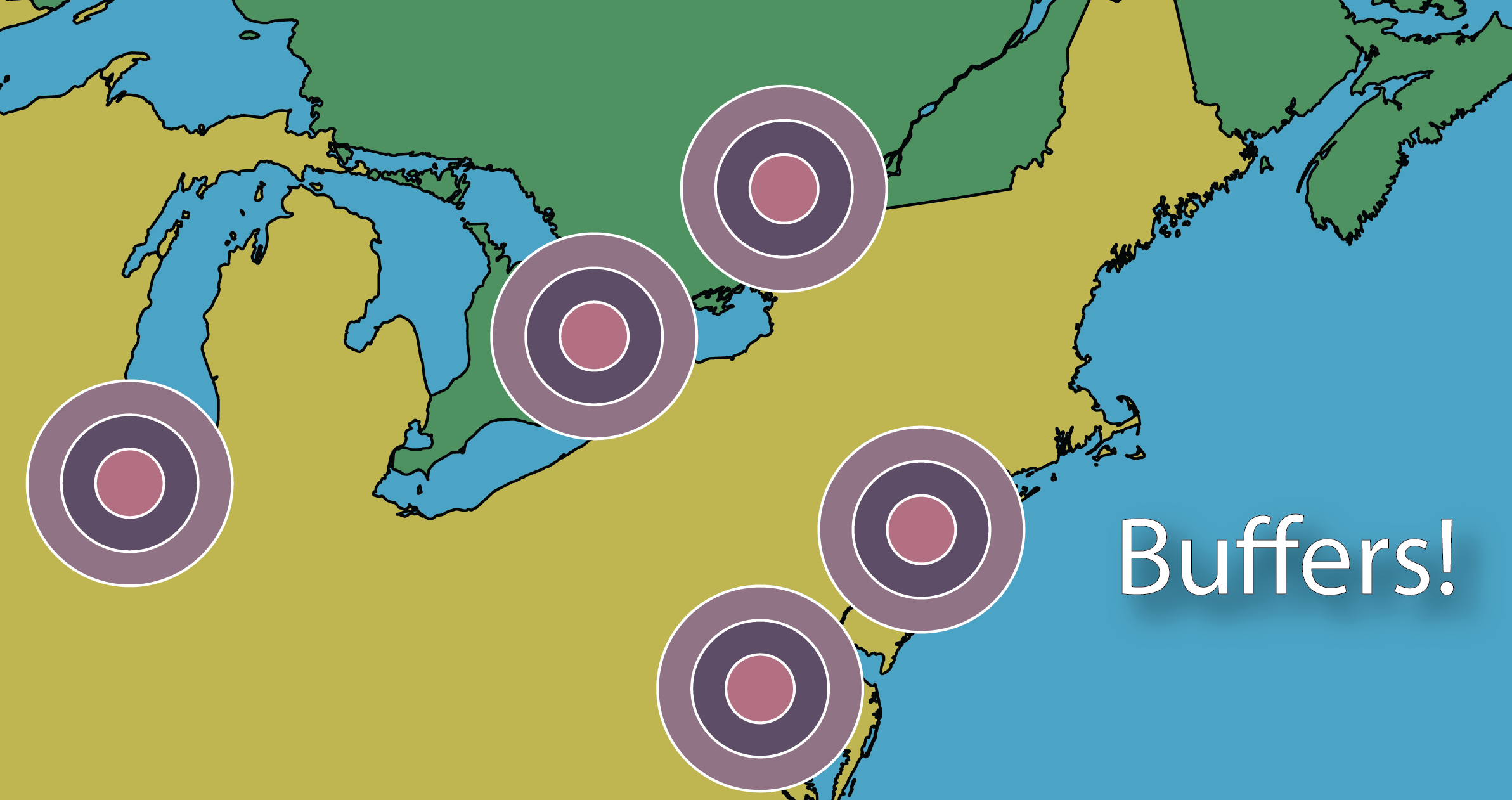
Buffer

A buffer is a zone around a specific map feature, that is measured in units of time or distance. A buffer is useful for proximity analysis or visualizing the areas that are within a certain distance from another feature (i.e. within school zones, or floodplains) 

6. Polygons/Areas

Areas / Polygons on a map

Enclosed Polygons on a map are often referred to as areas. Polygons can have attributes associated with them to represent a particular real-world entity such as postal code, economic identifiers, population demographics, environmental factors, or social behaviors.

The image above depicts areas on a map.

7. Coordinate systems

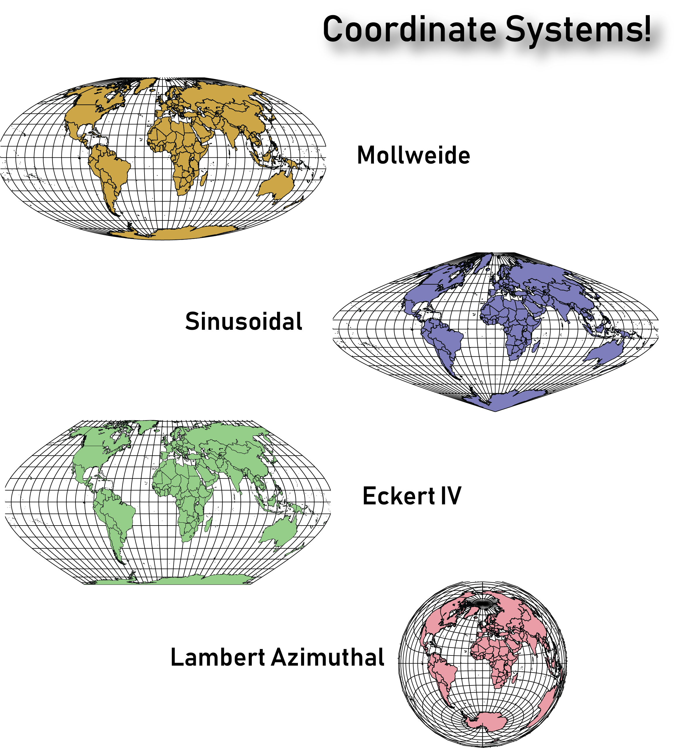
The planet is not flat, however, we routinely try to represent it in 2 dimensions on paper and screens. The Coordinate systems act as a reference framework that helps position features in order to make a map more useful for the purpose desired.

Coordinate Systems

It is important to note that there are thousands of coordinate systems, so it’s important to take the time to figure out which would work best for the type of map you intend on creating. Sometimes you’ll need to change the coordinate system from the one defined in the underlying map data, to help the map make more sense to the end-user. 

They say an artist is one who gives people something they didn’t know they were missing. If you happen to be an artist or know an artist (graphic designer) who seeks to give people direction – literally ‘direction’ – you’ve landed in the right place. Go ahead and share this article with like-minded map enthusiasts to begin learning and delivering high-quality maps the easy way. 

Sources:

https://researchguides.dartmouth.edu/gis/spatialanalysis

https://en.wikipedia.org/wiki/Buffer_(GIS)

What’s New? MAPublisher 10.5

MAPublisher 10.5 was released today and it has lots of new and improved features to make it even easier to make beautiful maps in Adobe Illustrator. If you’re new to MAPublisher, you can get a rundown of the full feature set here, and even try it free for 14 days. If you already use MAPublisher, we would love for you to tell us, on our Facebook page about your favourite feature or even share a map you’ve made!

Adobe 2020 Compatibility

This version of MAPublisher is fully compatible with Adobe Illustrator 2020 so go ahead and upgrade! Are you excited? We are too, but mostly about the other new stuff that is also included in this version of MAPublisher.

Interval Markers

Want to add mileage markers or mark intervals along roads, trails or other paths? Do it automatically using this new feature! Options for interval markers are found in the Path Utilities tool.

  • Define the distance of the interval and the units
  • Select and style the shape of the interval marker
  • Choose the font type, size, and spacing within the marker shape
  • Choose where to start and how to increment the markers


Map without interval markers - MAPublisher

Interval Marker Dialog Box

Map with interval markers - MAPublisher

Favourite Fonts

Tired of scrolling through hundreds of irrelevant fonts to find the ones you like? Now you can select your favourite fonts to appear at the top of the font selection list in Illustrator, saving you time and the reactivation of your repetitive stress injury. Recently used fonts will also appear at the top of the list.

NOTE: Screenshot is for illustrative purposes only. We do not advocate for the use of the Comic Sans font by anyone, at any time, for any reason. Ever.)

Customizable MAPublisher Toolbar

MAPublisher has a lot of tools. That’s a good thing, right? But let’s say you’re in a minimalist mood, or just want to simplify your life by tidying up the clutter. Customize the MAPublisher toolbar by selecting which tool categories to display on the toolbar, and hiding the ones you don’t use often. Ahh, now that’s better.

Customize the MAPublisher toolbar

Display Coordinate System Information on Scale Bar

Often, maps include the name of the coordinate systems in which the map is displayed, for reference purposes. It’s easy enough to create a text box and add this information manually, but we’re all about avoiding manual work.

Click the Display coordinate system checkbox in the Scale Bar to include the MAP View coordinate system as part of the scale bar.

  • Customize the label so that it reads the way you want it to
  • Decide on the positioning of the text above, below or beside the scale bar
  • Choose to center or align the label as you see fit

Add coordinate systems automatically

Other Useful Enhancements

MAP Attributes

You can now copy ‘read-only’ attribute values from MAP Attributes. Presumably, if you need or want to use this capability, the description of it probably makes sense to you.   

Copy MAP Objects

In the past, you could not automatically link copied objects to layers in the destination document if it contained layers with the same name as the layer in which the copied object originated. Still with us? 

Now you can automatically link objects (MAP Themes and Selections) to layers even if the destination document contains layers with the same name as the source document layer which is tied to the copied object. Now, grab a cup of peppermint tea and look at that neat and tidy toolbar for a few minutes to refocus. 

MAP Symbols 

New Oil & Gas symbols have been added to the MAP Symbols Library, as requested by users in this industry. 

MAPublisher makes it easy to make maps in Adobe Illustrator without the manual work, and with the flexibility to style and design maps while retaining the geospatial integrity of the map data. It’s the bridge between the art and science of cartography.

Updating and Enhancing Maps with Landsat 8

This guest blog post was written by Tom Patterson — one of the creators of the Equal Earth Projection, and Natural Earth Data, (you can read more about Tom here). Learn how he used Geographic Imager for Adobe Photoshop to create two maps from Landsat 8 imagery.

I am a big fan of Landsat 8 satellite images as a resource when making maps. Typically, I use these free images taken every 16 days for verifying and updating other geospatial datasets. I also transfer Landsat textures to shaded relief art in order to better evoke a sense of the physical environment.

The examples that follow demonstrate how I have used Landsat imagery to enhance two maps. The first example is Prince William Sound, Alaska, a map that I am presently working on. The second example is a Landsat mosaic of the Big Island of Hawaii. Both of my examples will give you a general idea on how to integrate Landsat images into your cartographic workflow—using Avenza’s GIS plugins for Adobe Photoshop and Illustrator—with a few technical tips thrown in for good measure. For in-depth information about using Landsat in Photoshop, refer to this tutorial.

Prince William Sound, Alaska

Prince William Sound, in south-central Alaska, is a spectacular place to map. Its sheltered waters are bounded by the lofty Chugach Mountains, indented by deep fjords with tidewater glaciers, and dotted by forest-cloaked islands. The problem I am facing is out-of-date geospatial data because of the rapidly melting of glaciers. For example, the positions of glaciers, lakes, rivers, and coastlines available in the National Hydro Dataset (NHD) have changed considerably since these data were collected between 2008 and 2012. In order to make an accurate map—if only for this year—I have had to re-digitize these vector elements using Landsat images as a reference.

For this task, I used “LandsatLook Images with Geographic Reference” downloaded from the Earth Explorer website. These quasi-natural color images, which come pre-made from bands 7, 5, and 3, clearly depict water bodies, vegetation, bare earth, and glaciers. They were perfect for mapping the changing landscape of Prince William Sound.

Tom Patterson Geographic ImagerNational Hydro Dataset lines overlaid on a LandsatLook image in Adobe Illustrator.
The lines do not match physical features on the more recent satellite image.

For reference, I used images taken on September 29, 2018, about the time when glacier melting ceases before the onset of winter. Images taken later in the fall are hampered by fresh snow cover and deep mountain shadows due to lower sun angles.

Because the LandsatLook images were in the same projection as my map, I could directly place and then register the images in the Adobe Illustrator file with MAPublisher. Had the projections been different, I first would have had to transform the LandsatLook images using the Geographic Imager plugin in Adobe Photoshop. Finally, I moved the LandsatLook images to a bottom layer and dimmed them for editing the lines with Illustrator’s Pencil tool. Using a Wacom tablet and stylus for editing lines greatly improved my drawing speed and accuracy.

If a 30-meter LandsatLook image lacks enough detail, you can increase the apparent resolution to 15 meters by applying panchromatic sharpening. Doing this will involve downloading all data bands that comprise the Landsat scene (a Zipped archive about 1 GB in size). Within this archive is Band 8, a grayscale image showing the same area as the LandsatLook image, but with double the resolution.

Tom Patterson Geographic ImagerComing into focus. A LandsatLook image before (left) and after (right) panchromatic sharpening.
Besides increasing detail, panchromatic sharpening also shifts colors.

Once Band 8 is downloaded, the first step is to enlarge the size of the LandsatLook image by 200 percent in Photoshop (Image/Image Size). Resample it using the Preserve Details (enlargement) option. Next, copy and paste Band 8 on top of the LandsatLook image. Then, in the Layers window, change the blending mode of the Band 8 layer from Normal to Luminosity. Finally, apply Curves adjustments to both layers until the tonal range of the combined image is to your liking. The pan-sharpened LandsatLook image will keep its georeferencing thanks to the Geographic Imager plugin.

Tom Patterson Geographic Imager Landsat8Use the Layers window in Photoshop to apply panchromatic sharpening. 
Selecting Luminosity blending mode for the Band 8 layer is key.

The Big Island, Hawaii

In 2017, I created a Landsat mosaic of the Big Island as a starting point for making two National Park Service maps: Ala Kahakai National Historic Trail and Hawaii Volcanoes National Park. I used the Landsat mosaic as a source for land cover textures—forest cover and historic lava flows (those that formed since 1800)—depicted on these maps. Compared to the Landsat mosaic, the map textures print very lightly in the interest of visual cleanliness.

Tom Patterson Geographic ImagerBig Island Landsat mosaic (left) and the maps of Ala Kahakai National Historic Trail (middle) and Hawaii Volcanoes National Park (right) derived from it. Click here to see a larger version of the Ala Kahakai map (5 MB) and here for the Hawaii Volcanoes map (6.4 MB).

The first step in creating a Landsat mosaic was downloading the appropriate image data. In a perfect world, a mosaic of the Big Island would only require four 185-kilometer-wide Landsat images. However, because of persistent cloudiness on the windward side of the island, ten images were needed to complete a nearly cloud-free mosaic. Using images taken in previous years was a necessity. When selecting older images with fewer clouds, I looked for those taken at about the same time of year to keep the lighting consistent. I then used the Clone Stamp and Spot Healing Brush tools in Photoshop to carefully delete any unavoidable clouds and their shadows from the mosaic. Fortunately, the few clouds that remained were in remote areas far from the main focus of the final maps.

Tom Patterson Geographic ImagerThe Big Island is covered by four overlapping Landsat images.

Tom Patterson Geographic Imager Landsat 8Clouds be gone. The Landsat mosaic before (left) and after (right) editing.

The Landsat mosaic was assembled in Photoshop using Geographic Imager (File/Automate/GI: Mosaic). In the Mosaic window, I selected the Maintain Layers option to ensure that each Landsat image was placed on a separate layer. I then added layer masks to each image layer to piece together the ten images with the goal of avoiding clouds. Although the masks themselves with feathered edges looked like a messy jig-saw puzzle, they combined to produce a seamless Landsat satellite image mosaic.

Tom Patterson Geographic Imager MosaicGeographic Imager’s Mosaic window.

I created the Big Island mosaic in natural color by compositing Bands 4, 3, and 2 as red, green, and blue channels, respectively, in Photoshop. I also brightened the forested areas with LandsatLook mosaic placed on the topmost Photoshop layer and with the layer opacity reduced (in normal blending mode). The natural color procedure is explained in detail here.

With a Landsat mosaic of the Big Island completed, my next task was extracting the forest and lava textures and applying them to the Ala Kahakai and Hawaii Volcanoes maps. But that was an involved procedure that will have to wait for another blog.

One more thing …

Since making the Big Island mosaic in 2017, the Puna district experienced volcanic activity in 2018 that covered a large area in lava and reconfigured the shoreline. Although Puna is the cloudiest area on the Big Island, I was lucky to find a recent cloud-free Landsat image that I then used to update the mosaic. You can download a GeoTIFF of the updated mosaic here (120 MB). It is in the public domain.

Tom Patterson Geographic ImagerPuna District, Hawaii, before (left) and after (right) the volcanic eruptions of 2018.

Cartographer Chronicles: Tom Patterson

The process of making maps can vary greatly depending on the cartographer and the purpose of the map. Tom Patterson, one of the cartographers behind the public domain data set Natural Earth and the popular website Shaded Relief, regards cartography as a creative process. He sees geospatial data as an artist would see paint on their palette. “They are raw materials from which the map is made,” says Patterson. “For me, the map making process starts with an online scavenger hunt for geospatial data, and ends with a visual depiction of the results of that scavenger hunt, a map.”

Patterson recently retired after 26 years with the U.S. National Park Service at the Harpers Ferry Center, located in West Virginia. Harpers Ferry Center is the media hub for the U.S. National Park Service, where most of the maps, exhibits, and publications for public consumption are produced.

Patterson is well-known for making maps with beautiful shaded relief effects, a technique that he has focused on for his entire career. It’s something he has a passion for and is a feature that he believes makes his maps unique. “When making a shaded relief, I go to great pains to portray the natural world in a beautiful and idealized manner, by combining shaded relief with land cover data, drop shadows, gradients and vignettes, with control and restraint,” says Patterson. “I ultimately want to create a shaded relief that readers will find attractive and which will blend harmoniously with the vector elements above.” Patterson prefers light, luminous colours for depicting terrain, and also tell a story. “A map is more than just a combination of points, lines, polygons, type and pixels. To me, a really good map is one that becomes much more than the sum of these parts,” he says. “Maps are an important form of communication, and they should effectively share the ideas of the cartographer to the map reader.”

When making graphically creative maps, you want to use tools that provide you with the most control. With MAPublisher, you can easily access and manipulate geospatial data using Adobe software. “MAPublisher and Geographic Imager bridge the gulf between graphical and GIS worlds.”

Patterson was an early-adopter of MAPublisher, a plug-in for Adobe Illustrator after learning about it in 1996 at the annual North American Cartographic Information Society (NACIS) conference. If you’ve ever used the Natural Earth data, you might be interested to know that most of the vector elements were created with MAPublisher and Adobe Illustrator.

He was also integral in the development of Geographic Imager when during a presentation about manipulating Digital Raster Elevation Model (DEM) data he commented that having a MAPublisher-like software for Adobe Photoshop would be useful. “My suggestion was heard by the President of Avenza, Ted Florence, who was in the audience. He put me in touch with the software development team at Avenza to brainstorm ideas about a GIS plug-in for Adobe Photoshop. Geographic Imager was the eventual result of our discussions.”

Along with his many contributions to the cartographic community, Patterson has held some important positions as the former president and current Executive Director of NACIS. Patterson has created accessible, open source data for global use (Natural Earth), he recently contributed to a new map projection that is taking the cartography and GIS world by storm; Equal Earth. “This equal-area pseudo-cylindrical projection has gained traction rapidly—it seems that cartographers and map users alike have had an unfilled need for world maps depicting countries at true size and presented in a pleasing manner,” he quips.

As an accomplished and respected veteran of the field, we asked that what advice Patterson would give to new cartographers, finding their way? “Seek out advice,” he states. “Map design and production is mostly a solitary task, and any map you create will seem easy-to-understand and logical to you since you are the one who made it. But, your readers may not see it that way,” says Patterson. “The easiest way to avoid these potential ‘failures to communicate’ is by showing drafts of your maps to people that are not family and close friends.”

Another tip that Patterson has for fledgeling cartographers, is to give readers a reason to slow down and read your map. “The trick in today’s media-saturated environment is to design a map that will catch your reader’s eye, ignite their curiosity, and draw them in. Give the most emphasis to the information you want them to remember long after they put down your map.”

Cartographer Chronicles: Thorfinn Tait

Cartographer Chronicles Thorfinn Tait

A teacher by day and a cartographer by night, Thorfinn Tait (a native of Scotland) has been teaching high school in Japan for almost 20 years while making maps of fantasy lands in his spare time.

Mapping is a hobby for Tait, and his deep love of atlases, along with fantasy role-playing games (known as RPGs), helped drive him towards creating his own maps of fantasy worlds. He started in 2005, making maps in Adobe Illustrator. His goal was to create an atlas of a fantasy world, that included the same variety of maps that you’d find in any traditional world atlas — topographical, political, thematic — along with all the tables of data typically found in an atlas. He chose to map the world of Mystara, a popular Dungeons & Dragons (D&D) campaign setting from the 80s and 90s.

Tait set out to compile all of the original maps of Mystara (more than 250 of them) into a cohesive whole. “One of my biggest struggles was trying to work out what projection Mystara’s maps used. But there was a fundamental disconnect for me in that Illustrator alone did not have the functions I needed,” says Tait. “For example, to change the projection of a map, I tried to use it in tandem with other GIS software, but it was very troublesome having to constantly import and export elements between programs.”

Map of Caldwen

©2019 Bruce A. Heard. World of Calidar™ Fantasy Setting.

While working on the Atlas of Mystara project, an original Mystara author made a return to the industry, and Tait volunteered to remake his maps in Illustrator. The year after, that same author commissioned Tait to map a new RPG world, the World of Calidar. Determined to avoid the same problems he’d encountered with Mystara, he began establishing dimensions of the new world and creating custom projections based on them. But, working between Adobe Illustrator, Adobe Photoshop and GIS software was still very complicated.

World of Calidar

©2018 Bruce A. Heard. World of Calidar™ Fantasy Setting.

I managed to complete the first assignment with just those tools, but as soon as I got my first commission, I invested it right back into my maps by purchasing MAPublisher and Geographic Imager.” With MAPublisher, a plug-in for Adobe Illustrator and Geographic Imager, a plug-in for Adobe Photoshop, Tait could work natively in both Illustrator and Photoshop.

“My favourite aspect of MAPublisher is without a doubt the custom coordinate system. It allows me to create resources for fantasy worlds just like they already exist for the real world, and then repurpose them across all of my maps,” says Tait. He also uses MAP Attributes and adds data to the world’s geography. “For example, it’s easy for me to track things like road and river lengths, land areas, dimensions of coastlines and political borders, and so on — MAPublisher calculates all of these things for me automatically.”

MAPublisher has allowed Tait to take his previous work and convert it to the newly established custom coordinate systems, without losing any of the GIS attributes he’d created over previous years. Tait also uses Geographic Imager to create Digital Elevation Models (DEMs) for the World of Calidar. DEMs can help bring maps to life, adding an intricate level of detail and depth.

World of Calidar

©2014 Bruce A. Heard. World of Calidar™ Fantasy Setting.

Tait’s tagline for his freelance business is “Mapping fantastic worlds with real-world accuracy”. “I couldn’t do this without MAPublisher and Geographic Imager,” he says. “The software allows me to create and work with data for a fantasy world just like other people map the real world, the only difference is that I am creating all the data myself!”

“MAPublisher has truly expanded my horizons as a cartographer and has also changed the course of my projects. Without it, my current work would simply not be practical — in fact, probably not possible at all.”

Tait is currently working on georeferencing existing Mystara maps and tagging elements with their original sources. Check out more of his mapping projects on his website!

Carto-Jargon 201: Cartography Terms Defined

In a previous blog post, we defined a few common cartography terms that you might be likely to encounter while using MAPublisher and Geographic Imager; however, that was just the tip of the iceberg when it comes to cartography and GIS jargon. Here, in no particular order, are several additional terms used by cartographers, GIS professionals and people who work with spatial imagery.

Topology

Topology is a key principle in GIS for data management and integrity, ensuring the data quality of spatial relationships is maintained. In general, a topological data model defines how spatial objects (point, line, and area features) are represented, and defines and enforces data integrity rules (for example, there should be no gaps between polygons).

Azimuth

The horizontal angle, measured in degrees, between a baseline drawn from a center point and another line drawn from the same point. Normally, the baseline points true north and the angle is measured clockwise from the baseline.

Neatline

All 2-dimensionally rendered maps have to compromise somewhat on accuracy, even if only just a little by moving or scaling features to improve readability. However, the neatline is never adjusted, making it the most accurate element on a map.

The neatline is the border defining the extent of geographic data on a map and separating the body of the map from the map margin. It demarcates map units such as meridians and parallels, and depending on the map projection and the units selected, the neatline may not have 90-degree corners.  

Geodatabase

A Geodatabase, a database or file structure used primarily to store, query, and manipulate spatial data, stores geometry, a spatial reference system, attributes, and behavioral rules for data. An advantage of geodatabases over shapefiles is that various types of geographic datasets can be collected within a geodatabase, including feature classes, attribute tables, raster datasets, network datasets, topologies, and many others.

Geoprocessing

Geoprocessing is an operation used to manipulate a GIS data resulting in a new set of data. Common geoprocessing operations include geographic feature overlay, feature selection and analysis, topology processing, raster processing, and data conversion. Geoprocessing allows for the definition, management, and analysis of information used to make decisions based on patterns within the GIS data.

Shapefile

An Esri Shapefile is a vector data storage format for storing the location, shape, and attributes of geographic features. A shapefile is stored as a set of related files and contains one feature class. An alternative to using shapefiles to store GIS data is a geodatabase, however, shapefiles have some advantages in terms of relative simplicity and wide-ranging compatibility with many applications. Related files contain additional information that is read by the shapefile when opening/importing in GIS applications, as long as these related files have the same name and reside in the same directory – the *.dbf (database) file contains attribute information, and the *.prj (projection) file contains coordinate system information. Shapefiles also have limitations such as the inability to support raster files, and large file sizes.

Buffer

A zone around a map feature measured in units of distance or time is called a buffer. Buffers are useful for proximity analysis.

Geodesy

Geodesy is the science concerned with the measurement and mathematical description of the size and shape of the earth and its gravitational fields. Geodesy includes the large-scale, extended surveys for determining positions and elevations of points, in which the size and shape of the earth must be taken into account to achieve accuracy.

Vector vs Raster

The terms vector and raster are encountered often in cartography though they are not often defined. In a nutshell,

Raster data is made up of pixels (sometimes referred to as grid cells). Each pixel can have a range of values used to represent data points. For example, in a satellite image, every pixel has a red, green and blue value.  

Vector data is not made up of a grid of pixels. Instead, vector graphics are comprised of vertices and paths where the vertices are x,y coordinates. In GIS systems, they are a latitude and longitude with a spatial reference frame.

Mosaic

A Mosaic is a single raster dataset composed of two or more merged raster datasets—for example, one image can be created by assembling multiple aerial photographs whose edges usually have been torn or cut selectively and matched to the imagery on adjoining images to form a continuous representation of a portion of the Earth’s surface.

Orthorectification

The process of correcting the geometry of an image so that it appears as though each pixel were acquired from directly overhead. Orthorectification is used to correct terrain distortion in aerial or satellite imagery.

Sources

http://wiki.gis.com/wiki/index.php/GIS_Glossary/
https://legacy.lib.utexas.edu/maps/glossary.html
https://gisgeography.com/spatial-data-types-vector-raster/

News Archive